SECTION 501-20A: Safety Belt System
| 2014 Mustang Workshop Manual
|
REMOVAL AND INSTALLATION
| Procedure revision date: 01/07/2013
|
Safety Belt Retractor and Pretensioner
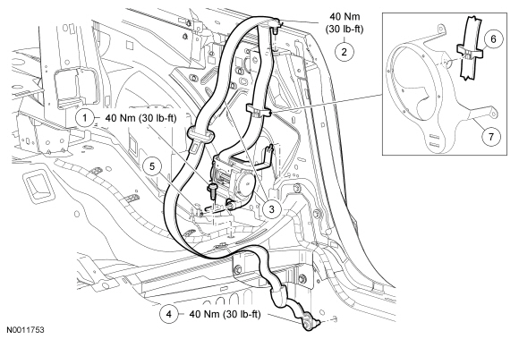
Safety Belt Retractor and Pretensioner — Coupe
NOTE:
RH shown, LH similar.

| Item
| Part Number
| Description
| | 1
| —
| Safety belt retractor and pretensioner anchor bolt (part of 611B08 RH/ 611B09 LH)
|
| 2
| —
| Belt Tension Sensor (BTS) cover (part of 611B08)
|
| 3
| —
| electrical connector (part of 611B08)
|
| 4
| —
| Safety belt presenter (part of 611B08 RH/ 611B09 LH)
|
| 5
| —
| D-ring (part of 611B08 RH/ 611B09 LH)
|
| 6
| —
| D-ring bolt (part of 611B08 RH/ 611B09 LH)
|
| 7
| 60262
| D-ring cover
|
| 8
| 611B08 RH/ 611B09 LH
| Safety belt retractor and pretensioner
|
| 9
| —
| Safety belt retractor and pretensioner electrical connector (part of 14A005)
|
| 10
| —
| Safety belt retractor and pretensioner bolt (part of 611B08 RH/ 611B09 LH)
|
Safety Belt Retractor and Pretensioner — Convertible
NOTE:
LH shown, RH similar.
| Item
| Part Number
| Description
| | 1
| W700883
| Safety belt retractor and pretensioner bolt
|
| 2
| —
| D-ring bolt (part of 611B09 LH/ 611B08 RH)
|
| 3
| 611B09 LH/ 611B08 RH
| Safety belt retractor and pretensioner
|
| 4
| —
| Safety belt anchor bolt (part of 611B09 LH/ 611B08 RH)
|
| 5
| —
| Safety belt retractor and pretensioner electrical connector (part of 14A005)
|
| 6
| —
| Secondary safety belt guide (part of 611B09 LH/ 611B08 RH)
|
| 7
| 18963
| Speaker bracket
|
Removal
 WARNING: All safety belt components must be inspected and corrected as part of any collision repair. Inspect all safety belt components as prescribed by Safety Belt Inspection and Repair After a Collision found in Section 501-20A General Procedures of this manual. Failure to follow this instruction may result in incorrect operation of the safety belt system and increase the risk of serious personal injury or death in a crash.
WARNING: Never disassemble or tamper with seat belt deployable components, including pretensioners, load limiters and inflators. Never back probe deployable device electrical connectors. Tampering or back probing may cause an accidental deployment and result in personal injury or death.
NOTE:
The air bag warning indicator illuminates when the correct Restraints Control Module (RCM) fuse is removed and the ignition is ON.
NOTE:
The Supplemental Restraint System (SRS) must be fully operational and free of faults before releasing the vehicle to the customer.
- Depower the
. For additional information, refer to Supplemental Restraint System (SRS) Depowering and Repowering in the General Procedures portion of
Section 501-20B
.
- Remove the D-ring and quarter trim panel(s).
- For coupe
, remove the cover, bolt, spacer and D-ring cover.
- Remove the lower quarter trim panel. For additional information, refer to
Section 501-05
.
- For convertible
, remove the upper and lower quarter trim panel. For additional information, refer to
Section 501-05
.
- Remove the cover, bolt, and D-ring.
- Remove the safety belt anchor bolt.
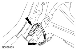
- For passenger side, disconnect the Belt Tension Sensor (BTS) electrical connector.
- For convertible, remove the secondary safety belt guide from the speaker bracket.
- Disconnect the safety belt retractor and pretensioner electrical connector.
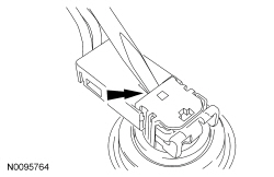
- Use a small screwdriver to lift up and release the Connector Position Assurance (CPA) clip and remove the electrical connector.
- Remove the bolt and safety belt retractor and pretensioner.
Installation
NOTICE:
To prevent component damage, the shipping clip on a new retractor must remain attached prior to the installation of the retractor to the vehicle.
NOTE:
For coupe, the presenter must be in the downward position for correct installation of the safety belt retractor.
NOTE:
Before installation, make sure the safety belt webbing is not twisted and the safety belts and buckles are accessible to the occupants.
- Install the bolt and safety belt retractor and pretensioner.
- Tighten to 40 Nm (30 lb-ft).
NOTICE:
The Connector Position Assurance (CPA) clip must be in the released position before installing the connector into the pretensioner. Failure to have the
clip in the released position may break the tabs on the
clip causing Diagnostic Trouble Codes (DTCs) to set in the Restraints Control Module (RCM).
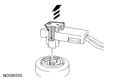
Connect the safety belt retractor and pretensioner electrical connector.
- Lift up the
clip and install the electrical connector fully into the safety belt retractor pretensioner and seat the
clip.
- For convertible, install the secondary safety belt guide to the speaker bracket.
- Install the safety belt anchor bolt.
- Tighten to 40 Nm (30 lb-ft).
- For passenger side, connect the
electrical connector.
- For convertible, install the bolt and D-ring.
- Tighten to 40 Nm (30 lb-ft).
- Install the quarter trim panel.
- For coupe
, install the lower quarter trim panel.
- For convertible
, install the upper and lower quarter trim panel.
NOTE:
If the D-ring cover is damaged or does not remain closed, install a new D-ring cover.
For coupe, install the D-ring bolt, spacer and cover.
- Tighten to 48 Nm (35 lb-ft).
- Repower the
. For additional information, refer to Supplemental Restraint System (SRS) Depowering and Repowering in the General Procedures portion of
Section 501-20B
.
- Check the active restraint system for correct operation. For additional information, refer to
Safety Belt System
in this section.