 WARNING: If the clockspring is not correctly centralized, it may fail prematurely. If in doubt, repeat the centralizing procedure. Failure to follow these instructions may increase the risk of serious personal injury or death in a crash.
SECTION 501-20B: Supplemental Restraint System
| 2014 Mustang Workshop Manual
|
REMOVAL AND INSTALLATION
| Procedure revision date: 01/07/2013
|
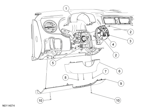
| Item | Part Number | Description |
|---|---|---|
| 1 | 3530 | Upper steering column shroud |
| 2 | — | Clockspring screws (part of 14A664) (2 required) |
| 3 | — | Driver air bag module electrical connector (part of 14A664) |
| 4 | 14A664 | Clockspring |
| 5 | — | Clockspring electrical connector (part of 14401) |
| 6 | 3530 | Lower steering column shroud |
| 7 | W707281 | Lower steering column shroud screw (2 required) |
| 8 | W706731 | Lower steering column shroud screw |
| 9 | 04459 | Steering column opening trim panel |
| 10 | — | Steering column opening trim panel screws |
Removal
NOTE: The air bag warning indicator illuminates when the correct Restraints Control Module (RCM) fuse is removed and the ignition is ON.
NOTE: The Supplemental Restraint System (SRS) must be fully operational and free of faults before releasing the vehicle to the customer.
Installation
WARNING: If the clockspring is not correctly centralized, it may fail prematurely. If in doubt, repeat the centralizing procedure. Failure to follow these instructions may increase the risk of serious personal injury or death in a crash.
NOTICE: Do not over-rotate the clockspring inner rotor. The internal ribbon wire is connected to the clockspring rotor. The internal ribbon wire acts as a stop and can be broken from its internal connection. Failure to follow this instruction may result in component damage and/or system failure.
NOTICE: If installing a new clockspring, do not remove the clockspring anti-rotation key until the steering wheel is installed. If the anti-rotation key has been removed before installing the steering wheel, the clockspring must be centered. Failure to follow this instruction may result in component damage and/or system failure.
NOTICE: To prevent damage to the clockspring, make sure the road wheels are in the straight-ahead position.
Install the steering wheel. For additional information, refer to Section 211-04 .