
software with appropriate hardware, or equivalent scan tool
SECTION 501-20B: Supplemental Restraint System
| 2014 Mustang Workshop Manual
|
REMOVAL AND INSTALLATION
| Procedure revision date: 01/07/2013
|
| Vehicle Communication Module (VCM) and Integrated Diagnostic System (IDS)
software with appropriate hardware, or equivalent scan tool |
| Item | Part Number | Description |
|---|---|---|
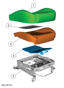
| 1 | 62900 | Cushion cover |
| 2 | 14D696 | Cushion heater mat |
| 3 | — | Cushion foam pad (part of Original Equipment (OE) Occupant Classification System (OCS)) |
| 4 | — | OCS (bladder, hose and pressure sensor) (part of OE ) |
| 5 | — | Seat track and cushion frame |
| Item | Part Number | Description |
|---|---|---|
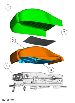
| 1 | 62900 | Cushion cover |
| 2 | 14D696 | Cushion heater mat |
| 3 | — | Cushion foam pad (part of 632A22) |
| 4 | — | OCS (bladder, hose and pressure sensor) (part of 632A22) |
| 5 | — | Seat track and cushion frame |
Removal
NOTICE: To prevent system failure, it is necessary to carry out the Occupant Classification System (OCS) reset when a front passenger seat cushion is disassembled, a new cover installed or an OCS service kit is installed. A scan tool is used to carry out the OCS reset.
NOTICE: Do not install a new heater mat on a front passenger seat cushion. Install a new Occupant Classification System (OCS) service kit. Failure to follow this instruction can cause incorrect OCS operation.
NOTE: The air bag warning indicator illuminates when the correct Restraints Control Module (RCM) fuse is removed and the ignition is ON.
NOTE: The Supplemental Restraint System (SRS) must be fully operational and free of faults before releasing the vehicle to the customer.
NOTE: Power seat shown, manual similar.
Disengage the OCS hose from the retainer.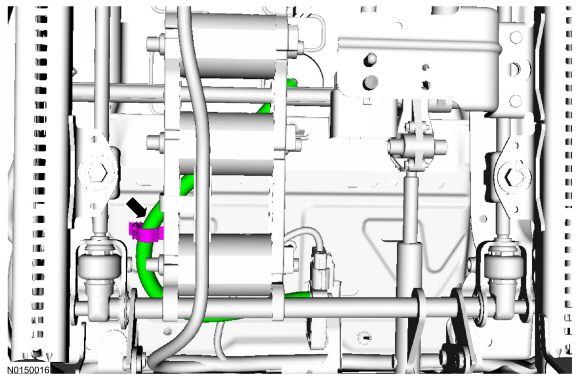
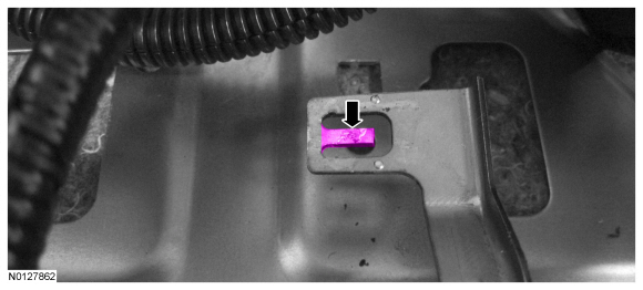
NOTICE: Using excessive force when bending the bracket tab can damage the OCS sensor housing.
NOTE: Power seat shown, manual similar.
Insert a flat head screw driver or other appropriate tool between the bracket and OCS pressure sensor. Pry the bracket retainer tab down.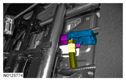
Installation
 WARNING: Occupant Classification System (OCS) parts are calibrated as an assembly and must only be replaced in the configuration they are sold. Never separate parts of an assembly. Failure to follow this instruction may result in incorrect operation of the OCS and increases the risk of serious personal injury or death in a crash.
WARNING: Make sure the front passenger seat repair is complete, the seat and all attached components (head restraint, seat side shield, etc.) are correctly assembled, and the seat is correctly installed to the vehicle before using System Reset to rezero the seat weight. Failure to follow these instructions may result in incorrect operation of the occupant classification system (OCS) and increases the risk of serious personal injury or death in a crash.
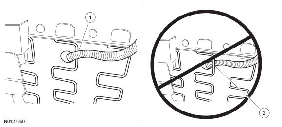
NOTICE: Failure to correctly route the Occupant Classification System (OCS) components may cause component failure and incorrect operation of the OCS .
Position the OCS hose and pressure sensor between the seat cushion wire support springs shown.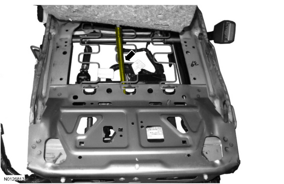
WARNING: Make sure the front passenger seat repair is complete, the seat and all attached components (head restraint, seat side shield, etc.) are correctly assembled, and the seat is correctly installed to the vehicle before using System Reset to rezero the seat weight. Failure to follow these instructions may result in incorrect operation of the occupant classification system (OCS) and increases the risk of serious personal injury or death in a crash.
NOTICE:
To prevent system failure, the following precautions must be taken before carrying out the Occupant Classification System (OCS) reset:
NOTE: A prepaid return postcard is provided with a new OCS service kit. The serial number for the new part and the Vehicle Identification Number (VIN) must be recorded and sent to Ford Motor Company.
If a new OCS service kit was installed, fill out the necessary information on the OCS traceability card and return it along with the complete inoperative OCS to Ford Motor Company.