SECTION 501-20B: Supplemental Restraint System
| 2014 Mustang Workshop Manual
|
REMOVAL AND INSTALLATION
| Procedure revision date: 01/07/2013
|
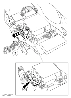
Restraints Control Module (RCM)
NOTE:
Parking brake control and selector lever partially omitted for clarity.
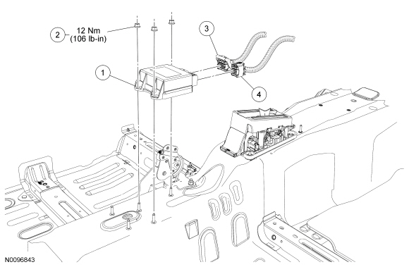
| Item
| Part Number
| Description
| | 1
| 14B321
| Restraints Control Module (RCM)
|
| 2
| W702751
| Nut (3 required)
|
| 3
| —
| large connector (part of 14A005)
|
| 4
| —
| small connector (part of 14401)
|
Removal
 WARNING: If a vehicle has been in a crash, inspect the restraints control module (RCM) and the impact sensor (if equipped) mounting areas for deformation. If damaged, restore the mounting areas to the original production configuration. A new RCM and sensors must be installed whether or not the airbags have deployed. Failure to follow these instructions may result in serious personal injury or death in a crash.
NOTICE:
When installing a new Restraints Control Module (RCM), it is necessary to carry out Programmable Module Installation (PMI). System failure may occur if
is not performed. For additional information, refer to
Section 418-01
.
NOTE:
When installing a new Restraints Control Module (RCM) always make sure the correct
is being installed. If an incorrect
is installed, DTCs will result.
NOTE:
The air bag warning indicator illuminates when the correct
fuse is removed and the ignition is ON.
NOTE:
The Supplemental Restraint System (SRS) must be fully operational and free of faults before releasing the vehicle to the customer.
- If installing a new
, carry out the steps necessary to prepare for Programmable Module Installation (PMI). For additional information, refer to
Section 418-01
.
- Depower the
. For additional information, refer to
Supplemental Restraint System (SRS) Depowering and Repowering
in the General Procedures portion of this section.
- Remove the floor console. For additional information, refer to the Removal and Installation procedures in
Section 501-12
.
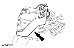
- Disconnect the large
connector.
- Pinch the thumb tab and pivot the Connector Position Assurance (CPA) lever back.
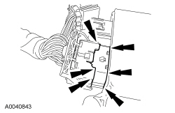
- Disconnect the
connector.
- Disconnect the small
electrical connector.
- Remove the 3 nuts and
.
Installation
WARNING: Always tighten the fasteners of the restraints control module (RCM) and impact sensor (if equipped) to the specified torque. Failure to do so may result in incorrect restraint system operation, which increases the risk of personal injury or death in a crash.
Position the
and install the nuts.
- Tighten to 12 Nm (106 lb-in).
- Connect the small
electrical connector.
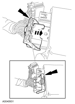
- Verify that the
lever is positioned back completely (as shown) before connecting the large
connector.
NOTICE:
Placing the large Restraints Control Module (RCM) electrical wiring connector into the
on an angle can cause bad electrical connections and damaged components.
Position the large
electrical connector into the
.
- Connect the large
connector.
- Insert the connector into the
.
- Push to lock the
lever thumb tab to the
.
- Install the floor console. For additional information, refer to the Removal and Installation procedures in
Section 501-12
.
- Repower the
. For additional information, refer to
Supplemental Restraint System (SRS) Depowering and Repowering
in the General Procedures portion of this section.
- If a new
was installed, carry out the appropriate steps necessary to complete
. For additional information, refer to
Section 418-01
.