
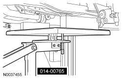
014-00765

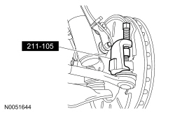
211-001 (TOOL-3290-D or equivalent)

303-1245

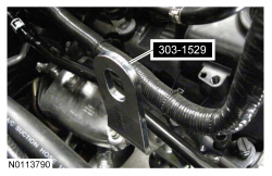
303-1529

303-F072
SECTION 502-00: Uni-Body, Subframe and Mounting System
| 2014 Mustang Workshop Manual
|
REMOVAL AND INSTALLATION
| Procedure revision date: 01/07/2013
|
| Powertrain Lift Table
014-00765 |
| Tie-Rod End Remover
211-001 (TOOL-3290-D or equivalent) |
| Eye, Engine Lift
303-1245 |
| Lift Eye, RH Front
303-1529 |
| Support Bar, Engine
303-F072 |
Removal and Installation
NOTE: Automatic transmission shown, manual transmission similar.
With the vehicle in NEUTRAL, position it on a hoist. For additional information, refer to Section 100-02 .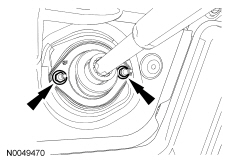
NOTE: Use a steering wheel holding device (such as Hunter® 28-75-1 or equivalent).
Using a suitable holding device, hold the steering wheel In the straight-ahead position.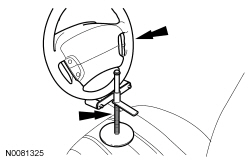
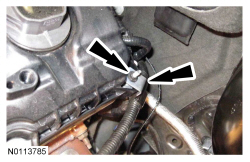
NOTE: LH shown, RH similar.
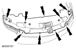
If equipped, remove the 4 nuts (2 shown) and the strut tower cross brace.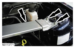
NOTE: RH shown, LH similar.
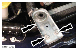
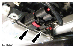
Remove the RH and LH engine mount-to-engine bracket mount nuts.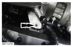
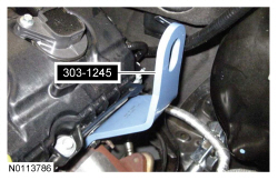
NOTICE: Do not position the legs of the Engine Support Bar on the fenders. instead, position the legs on the body structure near the suspension strut tower. Failure to follow these instructions may result in body damage.
Install the Engine Support Bar.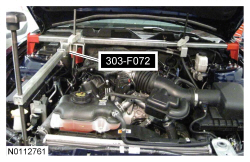
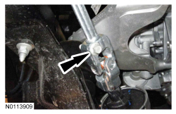
NOTE: RH shown, LH similar.
Loosen the 2 nuts for the crossmember brace.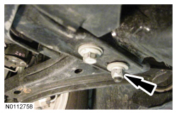
NOTE: RH shown, LH similar.
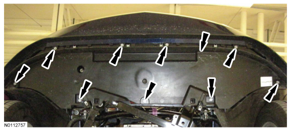
Remove the 6 bolts (2 shown), slide the crossmember forward and remove.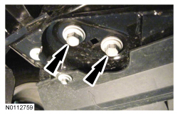
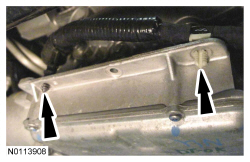
NOTE: RH shown, LH similar.
Remove the 4 rear subframe bolts.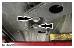
NOTE: RH shown, LH similar.
Remove the 4 front subframe nuts.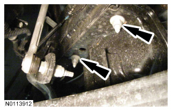
Installation
NOTE: RH shown, LH similar.
Loosely install the 4 rear subframe bolts.NOTE: RH shown, LH similar.
Install the crossmember brace and 6 bolts (2 shown).NOTE: RH shown, LH similar.
Tighten the 2 nuts for the crossmember brace to 65 Nm (48 lb-ft).NOTE: RH shown, LH similar.
Install the RH and LH engine mount bracket-to-engine mount nuts.NOTE: LH shown, RH similar.
If equipped, install the strut tower cross brace and the 4 nuts (2 shown)