SECTION 502-00: Uni-Body, Subframe and Mounting System
2014 Mustang Workshop Manual
REMOVAL AND INSTALLATION
Procedure revision date: 01/07/2013

Subframe — Front, 5.0L


Special Tool(s)
Powertrain Lift Table
014-00765
Tie-Rod End Remover
211-001 (TOOL-3290-D or equivalent)
Lifting Bracket Set, Engine
303-050 (T70P-6000)
Support Bar, Engine
303-F070
Support Bar, Engine
303-F072

Removal and Installation

  1. NOTE: Automatic transmission shown, manual transmission similar.

    With the vehicle in NEUTRAL, position it on a hoist. For additional information, refer to Section 100-02 .
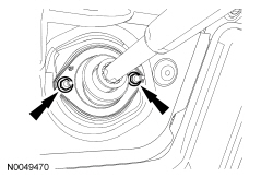
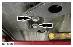
  1. Remove the 2 steering column dash boot bearing nuts.
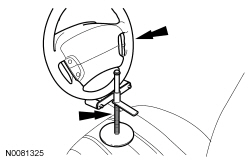
  1. NOTE: Use a steering wheel holding device (such as Hunter® 28-75-1 or equivalent).

    Using a suitable holding device, hold the steering wheel in the straight-ahead position.
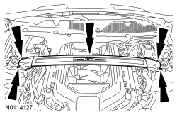
  1. If equipped, remove the 4 nuts (2 shown) and the strut tower cross brace.
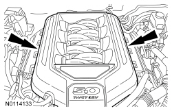
  1. NOTE: The engine appearance cover rubber grommets may remain on the cover. If so, remove the grommets from the cover and install them on the intake manifold before installing the cover.

    Remove the engine appearance cover.
  1. Remove the Air Cleaner (ACL) outlet pipe. For additional information, refer to Section 303-12 .
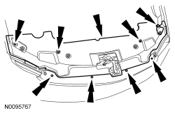
  1. Remove the 8 pin-type retainers and the radiator sight shield.
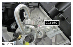
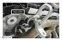
  1. Install an Engine Lifting Bracket on the rear of the RH cylinder head.
  1. NOTE: It may be necessary to install washers between the Engine Lifting Bracket and the cylinder head to prevent the Engine Lifting Bracket from contacting the valve cover while supporting the engine.

    Install an Engine Lifting Bracket on the side of the LH cylinder head.
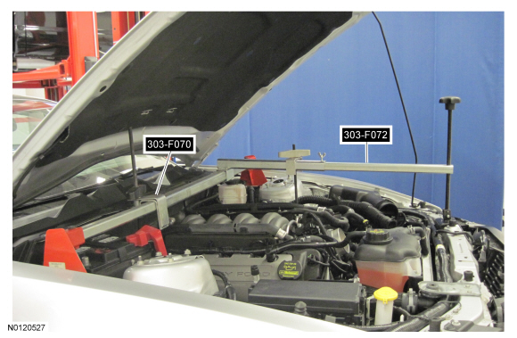
  1. NOTE: The draw screw and bracket from the heavy duty Engine Support Bar (303-F070) must be used with the light duty Engine Support Bar (303-F072). This will provide enough clearance between the draw screw bracket and the cowl.

    Install the Engine Support Bar.
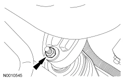
  1. NOTE: RH shown, LH similar.

    Remove the RH and LH engine support insulator nuts.
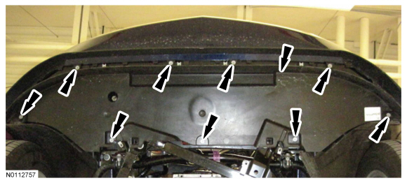
  1. Using the Engine Support Bar, raise the engine 25 mm (0.984 in).
  1. Remove the front tires and wheels. For additional information, refer to Section 204-04 .
  1. Remove the 9 bolts and the lower air deflector.
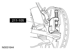
  1. Disconnect the outer LH and RH tie-rod ends.
  1. Disconnect the lower control arm.
  1. NOTE: RH shown, LH similar.

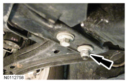
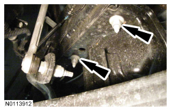
    Loosen the 2 nuts for the crossmember brace.
  1. NOTE: RH shown, LH similar.

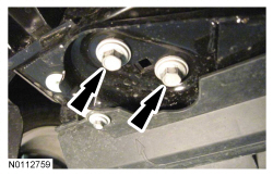
    Remove the 6 bolts (2 shown), slide the crossmember forward and remove.
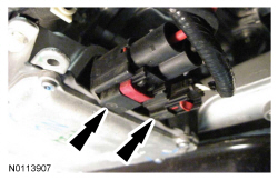
  1. Disconnect the 2 Electronic Power Assist Steering (EPAS) electrical connectors and the pin-type retainer.
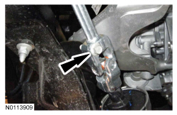
  1. Remove the steering shaft pinch bolt and disconnect the steering shaft.
  1. Mark the position of the 4 subframe nuts and 4 subframe bolts for reference during installation.
  1. NOTE: RH shown, LH similar.

    Remove the 4 rear subframe bolts.
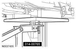
  1. Position the Powertrain Lift Table under the subframe assembly.
  1. NOTE: RH shown, LH similar.

    Remove the 4 front subframe nuts.
  1. Lower the subframe assembly from the vehicle.

Installation

  1. If installing a new subframe, transfer the steering rack and lower control arms to the new subframe. For additional information, refer to Section 211-02 and Section 204-01 .
  1. Position the subframe to the vehicle and loosely install the 4 front subframe nuts.
  1. NOTE: RH shown, LH similar.

    Loosely install the 4 rear subframe bolts.
  1. Use a suitable alignment tool with a 15 mm (0.59 in) OD shaft that is long enough to go through the subframe and body.
  1. Tighten the 4 rear subframe bolts in a cross pattern to 115 Nm (85 lb-ft).
  1. Tighten the 4 front subframe nuts.
  1. Remove the Powertrain Lift Table or suitable device from the subframe.
  1. Connect the lower control arms to the wheel spindles.
  1. Connect the outer LH and RH tie-rod ends.
  1. Connect the steering shaft and install the steering shaft pinch bolt.
  1. Connect the 2 EPAS electrical connectors and the pin-type retainer.
  1. NOTE: RH shown, LH similar.

    Install the crossmember brace and 4 bolts (2 shown).
  1. NOTE: RH shown, LH similar.

    Tighten the 2 nuts for the crossmember brace to 65 Nm (48 lb-ft).
  1. Install the lower air deflector and the 9 bolts.
  1. Install the front tires and wheels. For additional information, refer to Section 204-04 .
  1. Using the Engine Support Bar, lower the engine in position.
  1. Remove the engine support bar.
  1. Remove the RH and LH engine lifting eyes.
  1. Install the RH and LH engine support insulator nuts.
  1. Install the radiator sight shield and the 8 pin-type retainers.
  1. Install the ACL outlet pipe. For additional information, refer to Section 303-12 .
  1. NOTE: The engine appearance cover rubber grommets may remain on the cover. If so, remove the grommets from the cover and install them on the intake manifold before installing the cover.

    Install the engine appearance cover.
  1. If equipped, install the strut tower cross brace and the 4 nuts.
  1. Install the 2 steering column dash boot bearing nuts.