
014-00765

211-001 (TOOL-3290-D or equivalent)

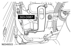
303-D087 (D93P-6001-A1)

303-F070

303-F072
SECTION 502-00: Uni-Body, Subframe and Mounting System
| 2014 Mustang Workshop Manual
|
REMOVAL AND INSTALLATION
| Procedure revision date: 01/07/2013
|
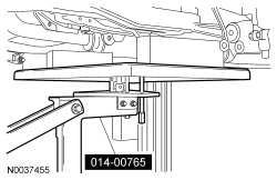
| Powertrain Lift Table
014-00765 |
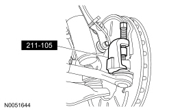
| Tie-Rod End Remover
211-001 (TOOL-3290-D or equivalent) |
| Lifting Bracket, Engine (2 required)
303-D087 (D93P-6001-A1) |
| Support Bar, Engine
303-F070 |
| Support Bar, Engine
303-F072 |
Removal
NOTE: Automatic transmission shown, manual transmission similar.
With the vehicle in NEUTRAL, position it on a hoist. For additional information, refer to Section 100-02 .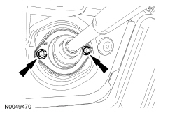
NOTE: Use a steering wheel holding device (such as Hunter® 28-75-1 or equivalent).
Using a suitable holding device, hold the steering wheel in the straight-ahead position.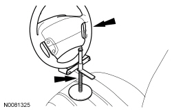
NOTE: RH shown, LH similar.
Remove the RH and LH engine support insulator nuts.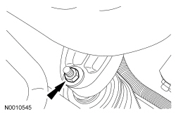
NOTE: The draw screw and bracket from the heavy duty Engine Support Bar (303-F070) must be used with the light duty Engine Support Bar (303-F072). This will provide enough clearance between the draw screw bracket and the cowl.
Install the Engine Support Bar.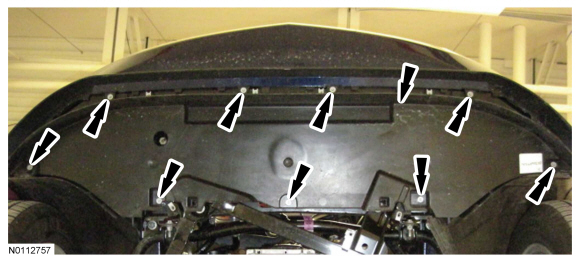
NOTE: RH shown, LH similar.
Loosen the 2 nuts for the crossmember brace.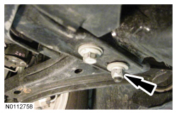
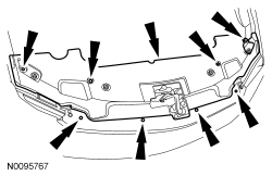
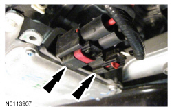
NOTE: RH shown, LH similar.
Remove the 6 bolts (2 shown), slide the crossmember forward and remove.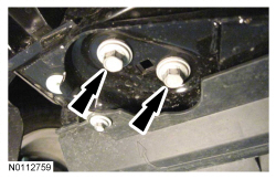
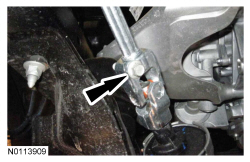
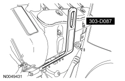
NOTE: RH shown, LH similar.
Remove the 4 rear subframe bolts.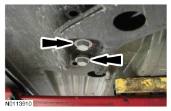
NOTE: RH shown, LH similar.
Remove the 4 front subframe nuts.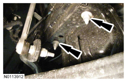
Installation
NOTE: RH shown, LH similar.
Loosely install the 4 rear subframe bolts.NOTE: RH shown, LH similar.
Install the crossmember brace and 4 bolts (2 shown).NOTE: RH shown, LH similar.
Tighten the 2 nuts for the crossmember brace to 65 Nm (48 lb-ft).