SECTION 303-00: Engine System — General Information
| 2014 Mustang Workshop Manual
|
GENERAL PROCEDURES
| Procedure revision date: 01/07/2013
|
Flywheel Inspection — 3.7L
Special Tool(s)
 | Dial Indicator Gauge with Holding Fixture
100-002 (TOOL-4201-C) or equivalent
|
 | Holding Tool, Flywheel
303-103 (T74P-6375-A)
|
NOTICE:
Do not clean the dual mass flywheel with any kind of fluid, use a dry cloth only or damage to the dual mass flywheel may occur.
NOTICE:
Do not clean the gap between the primary and secondary mass. Only clean the bolt connection surface and the clutch surface or damage to the flywheel may occur.
NOTE:
The dual mass flywheel normally has up to a total of 14 degrees (6.5 ring gear teeth) maximum rotational freeplay between the primary (bolted to crankshaft) and the secondary mass (clutch disc face).
- Check the transmission fluid level and fill to the correct level as necessary.
- With the engine operating at idle and the transmission in NEUTRAL, listen and check for unacceptable noise. Determine if any unacceptable noise is reduced when the clutch pedal is depressed.
- If unacceptable noise is identified, remove the transmission. For additional information, refer to
Section 308-03A
.
- Inspect the clutch slave cylinder for leaks. If a leak is identified, install a new clutch slave cylinder. For additional information, refer to
Section 308-02
.
- Inspect the sliding surfaces of the clutch release hub and bearing. Any scoring or burr should be removed with a fine grade of emery paper.
- Inspect the transmission input shaft for spline wear, scoring or burrs. Any scoring or burr should be removed with a fine grade of emery paper. If spline wear is identified, install a new transmission. For additional information, refer to
Section 308-03A
.
NOTE:
The clutch disc should be discarded due to possible hub spline wear or friction material wear.
Remove the clutch disc and pressure plate. For additional information, refer to
Section 308-01
.
- Inspect the clutch pressure plate and diaphragm spring segments and discard as necessary.
- Inspect the clutch pressure plate for scoring, cracks or discoloration. Any minor scoring or discoloration should be removed with a fine grade of emery cloth.
- Inspect the clutch diaphragm spring segments for damage, uneven height, scoring, cracks or discoloration. Any minor scoring or discoloration should be removed with a fine grade of emery cloth.
NOTE:
The flywheel cannot be machined.
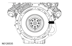
With the dual mass flywheel installed on the engine, inspect the dual mass flywheel surface for scoring, cracks, discoloration or damage. If any of these conditions exist, install a new flywheel.
- Inspect the dual mass flywheel friction control plate plastic piece between the primary and secondary mass for damage or melting and install a new dual mass flywheel if necessary.
NOTE:
The dual mass flywheel rotational freeplay inspection cannot be carried out if the friction control plate is damaged.
With the dual mass flywheel installed on the engine, inspect the dual mass flywheel rotational freeplay using the following Steps 12 through 15.
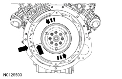
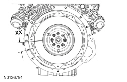
- Rotate the secondary mass counterclockwise and place a reference mark on the primary and secondary mass of the dual mass flywheel.
- Using light hand pressure, rotate the secondary mass clockwise to the end of the freeplay. Place a 2nd reference mark on the primary mass of the dual mass flywheel, in line with the reference mark on the secondary mass.
- Measure the rotational freeplay XX between the 2 reference marks on the primary mass of the dual mass flywheel. If the total rotational freeplay exceeds 14 degrees (6.5 ring gear teeth), install a new dual mass flywheel.
- With the dual mass flywheel installed on the engine, inspect the dual mass flywheel internal spring operation using the following Steps 17 through 19.
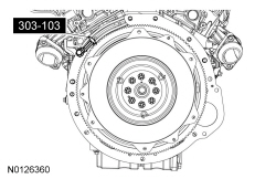
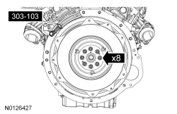
- Install the Flywheel Holding Tool.
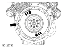
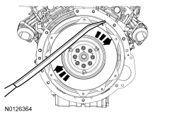
- Using a suitable long screwdriver or bar, firmly rotate the secondary mass clockwise. The secondary mass should begin to engage the internal spring past the freeplay movement of 14 degrees (6.5 ring gear teeth) maximum. The secondary mass should continue to rotate and engage the internal spring with increasing spring pressure. If the secondary mass does not rotate, install a new dual mass flywheel.
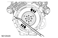
- Using a suitable long screwdriver or bar, firmly rotate the secondary mass counterclockwise. The secondary mass should begin to engage the internal spring past the freeplay movement of 14 degrees (6.5 ring gear teeth) maximum. The secondary mass should continue to rotate and engage the internal spring with increasing spring pressure. If the secondary mass does not rotate, install a new dual mass flywheel.
- Inspect the dual mass flywheel when removed from the engine and placed on a bench, using the following Steps 21 and 23.
NOTE:
Blocks must be placed under the dual mass flywheel to make sure it is level and stable.
Remove the bolts and the dual mass flywheel and place it on a firm and level surface.
- Discard the dual mass flywheel retaining bolts and remove the Flywheel Holding Tool.
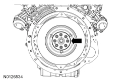
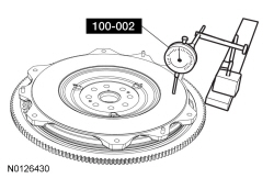
- Using the Dial Indicator Gauge with Holding Fixture, inspect the dual mass flywheel hub bush for wear and install new as necessary.
- Place a dial indicator gauge at a point on the outer upper surface of the secondary mass.
- Using light hand pressure, press downward at the opposite point on the outer upper surface of the secondary mass and note the deflection on the dial indicator gauge.
- Repeat this measurement at 45 degree intervals around the dual mass flywheel and note any deflection. Some axial movement of the secondary mass flywheel is normal, if the deflection exceeds 1.1 mm (0.043 in) at any point, install a new dual mass flywheel.
- Inspect the dual mass flywheel crankshaft mounting flange for residual thread locking compound or rust and clean as necessary.
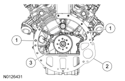
- Inspect the rear face of the engine block.
- Make sure that the 2 engine dowel pins are correctly installed and are not damaged, install new dowel pins as necessary.
- Inspect the engine block rear spacer plate for damage or warping and install new plate as necessary.
- Inspect the crankshaft flange for residual thread locking compound or rust, and clean as necessary.
- Inspect the transmission mounting face.
- Make sure that the 2 dowel pin holes are not elongated or damaged.
NOTE:
Install new dual mass flywheel retaining bolts.
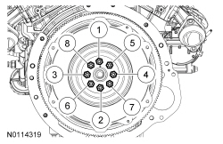
Install the dual mass flywheel and 8 new bolts finger tight.
- Install the Flywheel Holding Tool.
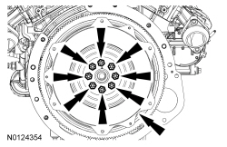
- Tighten the dual mass flywheel retaining bolts in the sequence shown to 80 Nm (59 lb-ft).
- Remove the Flywheel Holding Tool.
NOTE:
A new clutch disc should be installed due to possible hub spline wear or friction material wear.
Install the clutch disc and pressure plate. For additional information, refer to
Section 308-01
.
- Install the transmission. For additional information, refer to
Section 308-03A
.