SECTION 303-01A: Engine — 3.7L
| 2014 Mustang Workshop Manual
|
DESCRIPTION AND OPERATION
| Procedure revision date: 01/07/2013
|
The 3.7L (4V) is a (TiVct) V6 engine with the following features:
Engine Identification
For quick identification, refer to the safety certification decal.
Engine Code Information Label
The engine code information label, located on the front side of the valve cover, contains the following:
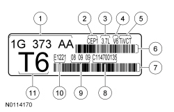
| Item | Description |
|---|---|
| 1 | Engine part number |
| 2 | Engine plant (Cleveland) |
| 3 | Engine displacement |
| 4 | Engine configuration |
| 5 | Twin independent VCT system |
| 6 | Bar code |
| 7 | Bar code |
| 8 | Running number |
| 9 | Engine build date (DDMMYY) |
| 10 | Plant shift line |
| 11 | Derivative code |
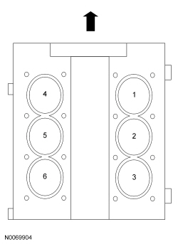
Engine Cylinder Identification
Exhaust Emission Control System
Operation and required maintenance of the exhaust emission control devices used on this engine is covered in the Powertrain Control/Emissions Diagnosis (PC/ED) manual.
Induction System
The SFI provides the fuel/air mixture needed for combustion in the cylinders. The 6 solenoid-operated fuel injectors:
Valve Train
The valve train uses Direct Acting Mechanical Buckets (DAMB). The camshaft lobes are positioned directly above mechanical buckets which are positioned on top of the valves.
Twin IndependentVariable Camshaft Timing (VCT) System
The twin independent VCT system allows variable control of intake valve closing which optimizes combustion at full load providing improved power and low speed torque (broadening the torque curve) which enables variable valve overlap which provides better fuel economy and emissions and provides optimized cold start operation with improved exhaust emissions.
PCV System
All engines are equipped with a closed-type PCV system recycling the crankcase vapors to the upper intake manifold.
Lubrication System
The engine lubrication system is of the force-feed type in which oil is supplied under full pressure to the crankshaft, connecting rod bearings, piston cooling jets, timing chain tensioners and VCT solenoids. The flow of oil to the valve tappets and valve train is controlled by a restricting orifice located in the cylinder head, valve train oil feed tubes. Die cast aluminum deep sump oil pan for 10,000 mile oil change intervals.
Oil Pump
The lubrication system is designed to provide optimum oil flow to critical components of the engine through its entire operating range.
The heart of the system is a positive displacement internal gear oil pump.
Generically, this design is known as a gerotor pump, which operates as follows:
Engine Oil Flow Illustration
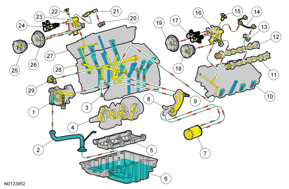
| Item | Part Number | Description |
|---|---|---|
| 1 | 6600 | Oil pump |
| 2 | 6622 | Oil pump screen and pickup tube |
| 3 | — | Piston oil cool valve (part of 6010) |
| 4 | 6303 | Crankshaft |
| 5 | 6C364 | Engine main bearing cap support |
| 6 | 6675 | Oil pan |
| 7 | 6731 | Oil filter |
| 8 | 6881 | Oil filter adapter |
| 9 | 9278 | Engine Oil Pressure (EOP) switch |
| 10 | 6049 | LH cylinder head |
| 11 | 6250 | Exhaust camshaft |
| 12 | 6250 | Intake camshaft |
| 13 | 6A258 | LH camshaft cap |
| 14 | 6K602 | LH valve train oil feed tube |
| 15 | 6K254 | LH secondary timing chain tensioner |
| 16 | 6B280 | LH camshaft mega cap |
| 17 | 6M280 | LH intake and exhaust camshaft Variable Camshaft Timing (VCT) oil control solenoid |
| 18 | 6C525 | LH exhaust camshaft VCT |
| 19 | 6C524 | LH intake camshaft VCT |
| 20 | 6A280 | RH camshaft cap |
| 21 | 6K602 | RH valve train oil feed tube |
| 22 | 6C270 | RH secondary timing chain tensioner |
| 23 | 6B280 | RH camshaft mega cap |
| 24 | 6M280 | RH intake and exhaust camshaft VCT oil control solenoid |
| 25 | 6C525 | RH exhaust camshaft VCT |
| 26 | 6C524 | RH intake camshaft VCT |
| 27 | 6049 | RH cylinder head |
| 28 | 6010 | Cylinder block |
| 29 | 6K254 | Primary timing chain tensioner |
Dual Mass Flywheel
NOTE: The dual mass flywheel normally has up to a total of 14 degrees (6.5 ring gear teeth) maximum rotational freeplay between the primary (bolted to crankshaft) and the secondary mass (clutch disc face).
A dual-mass flywheel is essentially two flywheels in one that provides spring cushioning to dampen torsional crankshaft vibrations and shock loading when the clutch is engaged. The two-piece assembly has a front "primary" mass and a rear "secondary" mass. The primary mass bolts to the crankshaft like an ordinary solid flywheel, and includes the ring gear for the starter. The clutch is bolted to the secondary mass, which is separate from the primary mass, but attached to it with a series of coil springs mounted sideways between the two. The springs allow just enough movement between the masses to transmit less engine vibration to the driveline, reduce some of the jarring and stress on the transmission and the remainder of the drivetrain when the clutch is engaged. The cushioning effect also reduces shock loading on the transmission for longer gear life and less noise.
Cooling System
The engine cooling system includes the following:
The channel cover plate is located under the engine front cover mounted to the block. It contains a timing chain idler and press and place gaskets separating engine coolant and engine oil. If oil or coolant is leaking from the weep hole, then a gasket has failed and must be replaced. A weep hole is provided on the front left side of the engine behind the generator. This weep hole create a reservoir for normal coolant seepage and evaporation. Every channel cover plate will have some leakage past the dynamic mechanical seal. Dampness and crusting around the weep hole is acceptable and an expected result of normal engine operation. Coolant spray or leakage amounts great enough to puddle should be addressed.