SECTION 303-01A: Engine — 3.7L
| 2014 Mustang Workshop Manual
|
IN-VEHICLE REPAIR
| Procedure revision date: 01/07/2013
|
Engine Support Insulators
Special Tool(s)
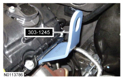
 | Eye, Engine Lift
303-1245
|
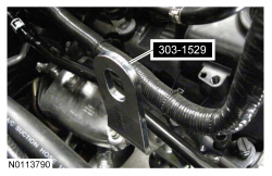
 | Lift Eye, RH Front
303-1529
|
 | Support Bar, Engine
303-F072
|
Engine Support Insulator — LH

| Item
| Part Number
| Description
| | 1
| W712530
| LH engine mount bracket-to-engine mount nut
|
| 2
| W500723
| LH engine mount bracket bolt (3 required)
|
| 3
| 6B033
| LH engine mount bracket
|
| 4
| W707641
| LH engine mount bolt (2 required)
|
| 5
| 6038
| LH engine mount
|
Engine Support Insulator — RH (View 1 of 2)

| Item
| Part Number
| Description
| | 1
| W520103
| Wiring harness retainer bracket nut
|
| 2
| —
| Wiring harness retainer bracket (part of 14B060)
|
| 3
| —
| Wiring harness retainer (part of 14B060) (manual transmission only)
|
| 4
| W520103
| Transmission cooling tube retainer nut (automatic transmission only)
|
| 5
| —
| Transmission cooling tubes retainer (part of 7H420) (automatic transmission only)
|
Engine Support Insulator — RH (View 2 of 2)

| Item
| Part Number
| Description
| | 1
| W712530
| RH engine mount bracket-to-engine mount nut
|
| 2
| W500723
| RH engine mount bracket bolt
|
| 3
| W714924
| RH engine mount bracket stud bolt (2 required)
|
| 4
| 6037
| RH engine mount bracket
|
| 5
| W707641
| RH engine mount bolt (2 required)
|
| 6
| 6038
| RH engine mount
|
Removal
All engine support insulator
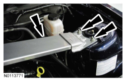
NOTE:
LH shown, RH similar.
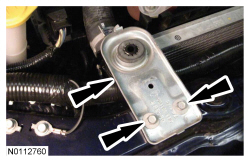
If equipped, remove the 4 nuts (2 shown) and the strut tower cross brace.
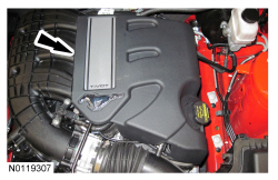
- If equipped, detach the 2 retainers and remove the engine appearance cover.
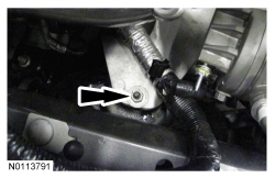
NOTE:
Both the RH and LH engine support insulator nuts must be removed to allow the engine to be raised.
NOTE:
RH shown, LH similar.
Remove the RH and LH engine mount-to-engine bracket mount nuts.
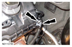
- Remove the nut from the rear LH valve cover stud bolt and position the generator wiring harness aside.
- Install the LH engine lift eye.
- Install the RH front engine lift eye.
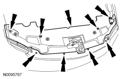
- Remove the 8 pin-type retainers and the radiator sight shield.
- Remove the 2 bolts and the RH radiator support bracket.
LH engine support insulator
- Remove the engine Air Cleaner (ACL) and
outlet pipe. For additional information, refer to
Section 303-12
.
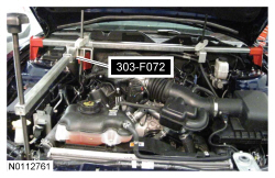
NOTICE:
Do not position the legs of the Engine Support Bar on the fenders. Instead, position the legs on the body structure near the suspension strut tower. Failure to follow these instructions may result in body damage.
Install the Engine Support Bar and raise the LH side of the engine 10 mm (0.393 in).
- Remove the 3 bolts and the LH engine mount bracket.
- Remove the 2 bolts and the LH engine mount.
RH engine support insulator
- Remove the battery tray. For additional information, refer to
Section 414-01
.
NOTICE:
Do not position the legs of the Engine Support Bar on the fenders. Instead, position the legs on the body structure near the suspension strut tower. Failure to follow these instructions may result in body damage.
Install the Engine Support Bar and raise the RH side of the engine 10 mm (0.393 in).
- Remove the 2 bolts and the RH exhaust manifold heat shield.
- If equipped with automatic transmission, remove the wiring harness retainer bracket and the transmission cooling tube retainer nuts from the RH engine mount bracket stud bolts and position aside.
- If equipped with manual transmission, remove the wiring harness retainer bracket nut and the wiring harness retainer from the RH engine mount bracket stud bolts and position aside.
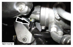
- Remove the 2 RH engine mount bracket stud bolts.
- Detach the wiring harness retainer from the A/C compressor stud bolt.
- Remove the bolt and the RH engine mount bracket.
- Remove the 2 bolts and the RH engine mount.
Installation
RH engine support insulator
- Install the RH engine mount and the 2 bolts.
- Tighten to 55 Nm (41 lb-ft).
- Install the RH engine mount bracket and the 2 stud bolts and bolt.
- Tighten to 55 Nm (41 lb-ft).
- Attach the wiring harness retainer to the A/C compressor stud bolt.
- If equipped with manual transmission, install the wiring harness retainer bracket nut and the wiring harness retainer to the RH engine mount bracket stud bolt.
- Tighten to 20 Nm (177 lb-in).
- If equipped with automatic transmission, install the wiring harness retainer bracket and the transmission cooling tube retainer nuts to the RH engine mount bracket stud bolts.
- Tighten to 20 Nm (177 lb-in).
- Install the RH exhaust manifold heat shield and the 2 bolts.
- Tighten to 12 Nm (106 lb-in).
- Install the battery tray. For additional information, refer to
Section 414-01
.
LH engine support insulator
- Install the LH engine mount and the 2 bolts.
- Tighten to 55 Nm (41 lb-ft).
- Install the LH engine mount bracket and the 3 bolts.
- Tighten to 55 Nm (41 lb-ft).
- Install the engine
and
outlet pipe. For additional information, refer to
Section 303-12
.
All engine support insulator
- Install the RH radiator support bracket and the 2 bolts.
- Tighten to 10 Nm (89 lb-in).
- Install the radiator sight shield and the 8 pin-type retainers.
- Position the generator wiring harness on the rear LH valve cover stud bolt and install the nut.
- Tighten to 10 Nm (89 lb-in).
NOTE:
RH shown, LH similar.
Install the RH and LH engine mount bracket-to-engine mount nuts.
- Tighten to 63 Nm (46 lb-ft).
- If equipped, install the appearance cover.
NOTE:
LH shown, RH similar.
If equipped, install the strut tower cross brace and the 4 nuts (2 shown).
- Tighten to 35 Nm (26 lb-ft).