SECTION 303-01A: Engine — 3.7L
| 2014 Mustang Workshop Manual
|
IN-VEHICLE REPAIR
| Procedure revision date: 01/07/2013
|
| Item | Part Number | Description |
|---|---|---|
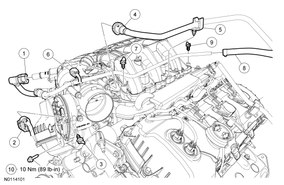
| 1 | 6A664 | PCV tube quick connect coupling |
| 2 | — | Throttle Body (TB) electrical connector (part of 12C508) |
| 3 | — | TB electrical connector wiring harness pin-type retainer (part of 12C508) |
| 4 | 9J280 | Evaporative Emission (EVAP) tube |
| 5 | — | EVAP hose retainer (part of 9J280) |
| 6 | — | EVAP canister purge valve electrical connector (part of 12C508) |
| 7 | — | EVAP canister purge valve electrical connector wiring harness pin-type retainer (part of 12C508) |
| 8 | — | Brake booster vacuum hose (part of 9C482) |
| 9 | — | Wiring harness pin-type retainer (part of 12C508) |
| 10 | W503275 | Upper intake manifold support bracket bolt |
| Item | Part Number | Description |
|---|---|---|
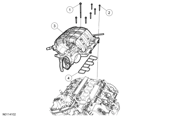
| 1 | W715096 | Upper intake manifold bolt |
| 2 | 9Y450 | Upper intake manifold bolt (6 required) |
| 3 | 9424 | Upper intake manifold |
| 4 | 9H486 | Upper intake manifold gasket |
Removal
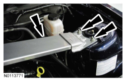
NOTE: LH shown, RH similar.
If equipped, remove the 4 nuts (2 shown) and the strut tower cross brace.
Installation
NOTICE: If the engine is repaired or replaced because of upper engine failure, typically including valve or piston damage, check the intake manifold for metal debris. If metal debris is found, install a new intake manifold. Failure to follow these instructions can result in engine damage.
Using new gaskets, install the upper intake manifold and tighten the 7 bolts in the sequence shown in 2 stages.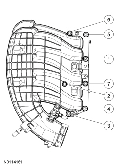
NOTE: LH shown, RH similar.
If equipped, install the strut tower cross brace and the 4 nuts (2 shown).