
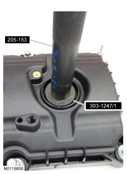
205-153 (T80T-4000-W)

205-142 (T80T-4000-J)

303-1247/2

303-1247/1
SECTION 303-01A: Engine — 3.7L
| 2014 Mustang Workshop Manual
|
IN-VEHICLE REPAIR
| Procedure revision date: 01/07/2013
|
| Handle
205-153 (T80T-4000-W) |
| Installer, Differential Bearing Cone
205-142 (T80T-4000-J) |
| Installer, Spark Plug Tube Seal
303-1247/2 |
| Remover, Spark Plug Tube Seal
303-1247/1 |
| Item | Specification |
|---|---|
| Motorcraft® High Performance Engine RTV Silicone
TA-357 | WSE-M4G323-A6 |
| Motorcraft® Metal Surface Prep
ZC-31-A | — |
| Motorcraft® Silicone Gasket Remover
ZC-30 | — |
| Item | Part Number | Description |
|---|---|---|
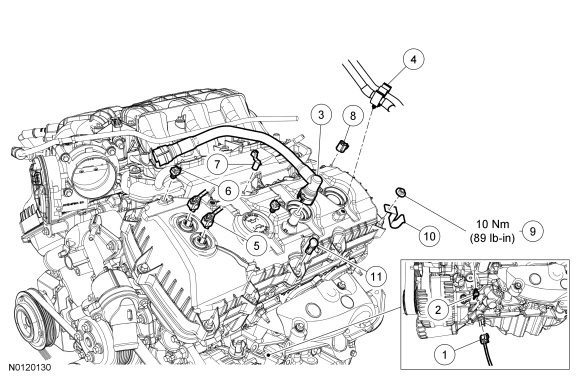
| 1 | — | Engine Oil Pressure (EOP) switch electrical connector (part of 12C508) |
| 2 | — | EOP switch electrical connector wiring harness pin-type retainer (part of 12C508) |
| 3 | 6758 | Crankcase ventilation tube |
| 4 | — | Fuel supply tube and Evaporative Emission (EVAP) tube retainer (part of 9J280) |
| 5 | — | LH Variable Camshaft Timing (VCT) electrical connector (part of 12C508) (2 required) |
| 6 | — | LH valve cover wiring harness pin-type retainer (part of 12C508) (2 required) |
| 7 | — | LH valve cover stud bolt wiring harness retainer (part of 12C508) |
| 8 | — | LH valve cover stud bolt wiring harness retainer (part of 12C508) |
| 9 | W701014 | LH valve cover stud bolt wiring harness bracket nut |
| 10 | — | LH valve cover stud bolt wiring harness bracket (part of 14B060) |
| 11 | — | LH valve cover stud bolt wiring harness retainer (part of 14B060) |
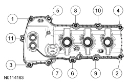
| Item | Part Number | Description |
|---|---|---|
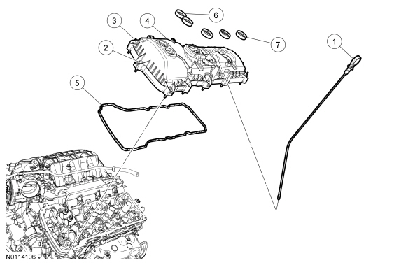
| 1 | 6750 | Oil level indicator |
| 2 | 6C519 | Valve cover bolt (4 required) |
| 3 | 6C519 | Valve cover stud bolt (7 required) |
| 4 | 6582 | LH valve cover |
| 5 | 6584 | LH valve cover gasket |
| 6 | 6C535 | Variable Camshaft Timing (VCT) solenoid seal (2 required) |
| 7 | 6C535 | Spark plug tube seal (3 required) |
Removal
NOTICE: During engine repair procedures, cleanliness is extremely important. Any foreign material, including any material created while cleaning gasket surfaces that enters the oil passages, coolant passages or the oil pan, may cause engine failure.
NOTE: LH shown, RH similar.
If equipped, remove the 4 nuts (2 shown) and the strut tower cross brace.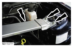
NOTICE: While removing the valve cover do not apply excessive force to the Variable Camshaft Timing (VCT) oil control solenoid or damage may occur.
NOTICE: If the Variable Camshaft Timing (VCT) oil control solenoid sticks to the VCT seal, carefully wiggle the valve cover until the bond breaks free or damage to the VCT seal and VCT oil control solenoid may occur.
NOTE: The plastic electrical connector on the VCT oil control solenoid will rotate approximately 12 degrees inside the steel housing, which is normal.
Loosen the 7 stud bolts, 4 bolts and remove the LH valve cover.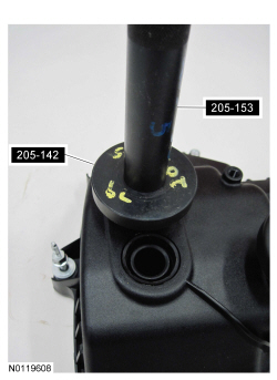
Installation
NOTE: Installation of new seals is only required if damaged seals were removed.
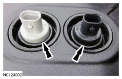
Using the VCT Spark Plug Tube Seal Installer and Handle, install new spark plug tube seals.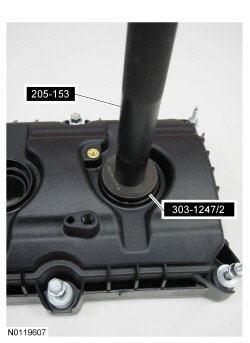
NOTE: Installation of new seals is only required if damaged seals were removed.
Using the Differential Bearing Cone Installer and Handle, install new VCT solenoid seal(s).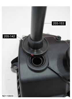
NOTICE: Failure to use the correct Motorcraft® High Performance Engine RTV Silicone may cause the engine oil to foam excessively and result in serious engine damage.
NOTE: If the valve cover is not installed and the fasteners tightened within 4 minutes, the sealant must be removed and the sealing area cleaned. To clean the sealing area, use silicone gasket remover and metal surface prep. Failure to follow this procedure can cause future oil leakage.
Apply an 8 mm (0.31 in) bead of Motorcraft® High Performance Engine RTV Silicone to the engine front cover-to-LH cylinder head joints.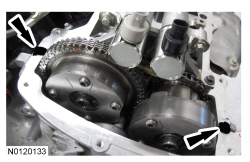
NOTE: LH shown, RH similar.
If equipped, install the strut tower cross brace and the 4 nuts (2 shown).