
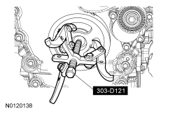
303-D121

205-153 (T80T-4000-W)

300-OTC1819E

303-1530

205-142 (T80T-4000-J)

205-150 (T80T-4000-S)

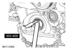
303-409 (T92C-6700CH)

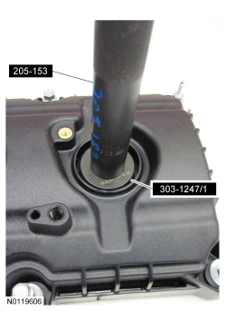
303-1247/1

303-D089 (D93P-6001-A3) or equivalent

303-D055 (D85L-6000-A)

303-1248
SECTION 303-01A: Engine — 3.7L
| 2014 Mustang Workshop Manual
|
DISASSEMBLY
| Procedure revision date: 04/03/2013
|
| 3 Jaw Puller
303-D121 |
| Handle
205-153 (T80T-4000-W) |
| 2,200# Floor Crane, Fold Away
300-OTC1819E |
| Hold Down, Secondary Chain
303-1530 |
| Installer, Differential Bearing Cone
205-142 (T80T-4000-J) |
| Installer, Spindle Bearing
205-150 (T80T-4000-S) |
| Remover, Oil Seal
303-409 (T92C-6700CH) |
| Remover, VCT Spark Plug Tube Seal
303-1247/1 |
| Spreader Bar
303-D089 (D93P-6001-A3) or equivalent |
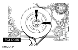
| Strap Wrench
303-D055 (D85L-6000-A) |
| Tool, Camshaft Holding
303-1248 |
| Item | Specification |
|---|---|
| Motorcraft® Metal Surface Prep
ZC-31-A | — |
| Motorcraft® Silicone Gasket Remover
ZC-30 | — |
 WARNING: Do not breathe dust or use compressed air to blow dust from storage containers or friction components. Remove dust using government-approved techniques. Friction component dust may be a cancer and lung disease hazard. Exposure to potentially hazardous components may occur if dusts are created during repair of friction components, such as brake pads and clutch discs. Exposure may also cause irritation to skin, eyes and respiratory tract, and may cause allergic reactions and/or may lead to other chronic health effects. If irritation persists, seek medical attention or advice. Failure to follow these instructions may result in serious personal injury.
NOTICE: During engine repair procedures, cleanliness is extremely important. Any foreign material, including any material created while cleaning gasket surfaces that enters the oil passages, coolant passages or the oil pan, may cause engine failure.
NOTE: For additional information, refer to the exploded view under the Assembly procedure in this section.
Engines with automatic transmission
Engines with manual transmission
NOTICE: Loosen the bolts evenly to prevent clutch pressure plate damage.
NOTE: If the parts are to be reused, index-mark the pressure plate to the flywheel.
Remove the 6 pressure plate bolts, remove the pressure plate and the clutch disc.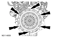
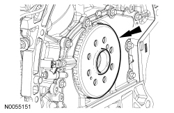
NOTE: The dual mass flywheel normally has up to a total of 14 degrees (6.5 ring gear teeth) maximum rotational freeplay between the primary (bolted to crankshaft) and the secondary mass (clutch disc face).
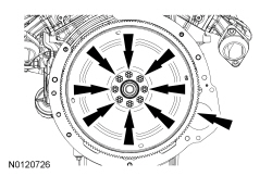
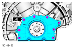
Remove the 8 bolts and the dual mass flywheel.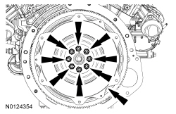
All engines
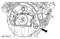
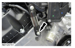
NOTE: Install the engine stand bolts into the cylinder block only. Do not install the bolts into the oil pan.
Using the Floor Crane and Spreader Bar, mount the engine on a suitable engine stand.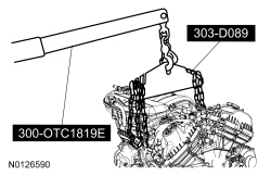
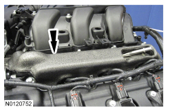
NOTICE: If the engine is repaired or replaced because of upper engine failure, typically including valve or piston damage, check the intake manifold for metal debris. If metal debris is found, install a new intake manifold. Failure to follow these instructions can result in engine damage.
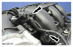
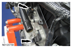
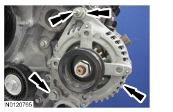
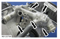
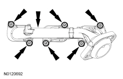
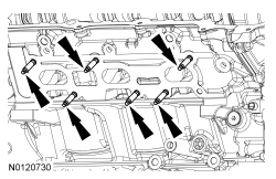
Loosen the 7 bolts and remove the upper intake manifold.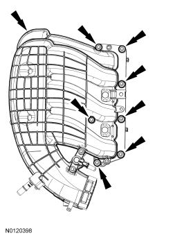
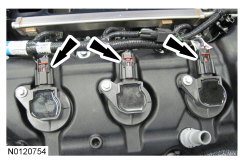
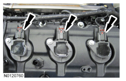
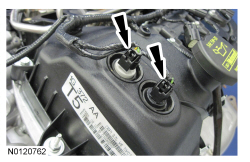
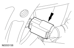
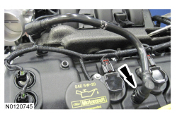
NOTE: When removing the ignition coil-on-plugs, a slight twisting motion will break the seal and ease removal.
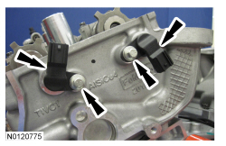
Remove the 3 bolts and the 3 LH ignition coil-on-plugs.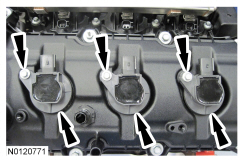
NOTICE: Only use hand tools when removing the spark plugs, or damage may occur to the cylinder head or spark plug.
NOTE: Use compressed air to remove any foreign material in the spark plug well before removing the spark plugs.
Remove the 3 LH spark plugs.NOTICE: While removing the valve cover do not apply excessive force to the Variable Camshaft Timing (VCT) oil control solenoid or damage may occur.
NOTICE: If the Variable Camshaft Timing (VCT) oil control solenoid sticks to the VCT seal, carefully wiggle the valve cover until the bond breaks free or damage to the VCT seal and VCT oil control solenoid may occur.
NOTE: The plastic electrical connector on the VCT oil control solenoid will rotate approximately 12 degrees inside the steel housing, which is normal.
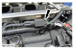
Loosen the 7 stud bolts, 4 bolts and remove the LH valve cover.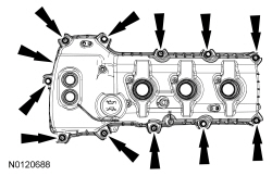
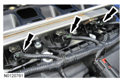
NOTE: When removing the ignition coil-on-plugs, a slight twisting motion will break the seal and ease removal.
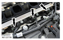
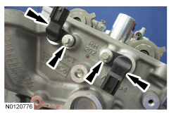
Remove the 3 bolts and the 3 RH ignition coil-on-plugs.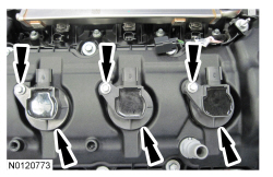
NOTICE: Only use hand tools when removing the spark plugs, or damage may occur to the cylinder head or spark plug.
NOTE: Use compressed air to remove any foreign material in the spark plug well before removing the spark plugs.
Remove the 3 RH spark plugs.NOTICE: While removing the valve cover do not apply excessive force to the Variable Camshaft Timing (VCT) oil control solenoid or damage may occur.
NOTICE: If the Variable Camshaft Timing (VCT) oil control solenoid sticks to the VCT seal, carefully wiggle the valve cover until the bond breaks free or damage to the VCT seal and VCT oil control solenoid may occur.
NOTE: The plastic electrical connector on the VCT oil control solenoid will rotate approximately 12 degrees inside the steel housing, which is normal.
Loosen the 8 stud bolts, 3 bolts and remove the RH valve cover.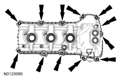
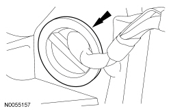
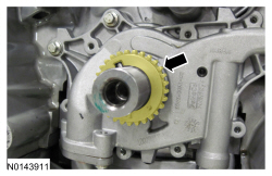
NOTE: The front cover radial seal must be replaced.
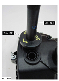
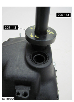
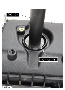
NOTE: Use Spindle Bearing Installer 205-150 to remove the seal.
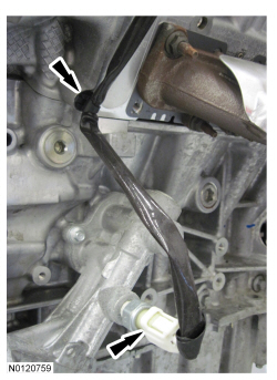
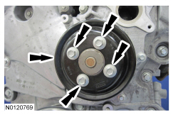
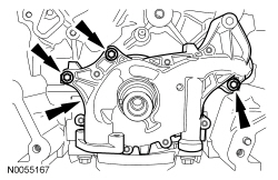
Using the Spindle Bearing Installer and Handle, remove the front cover radial seal from the rear side of the front cover.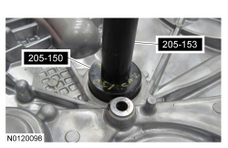
NOTE: The Camshaft Holding Tool will hold the camshafts in the Top Dead Center (TDC) position.
Install the Camshaft Holding Tool onto the flats of the LH camshafts.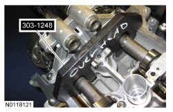
NOTE: The Camshaft Holding Tool will hold the camshafts in the TDC position.
Install the Camshaft Holding Tool onto the flats of the RH camshafts.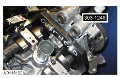
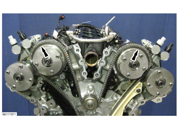
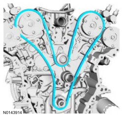
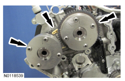
NOTE: The following 3 steps are for primary timing chains that the colored links are not visible.
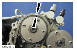
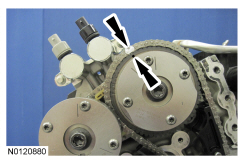
NOTE: The crankshaft sprocket timing mark should be between the 2 colored links.
Mark the 2 timing chain links that align with the timing mark on the crankshaft sprocket as shown.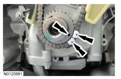
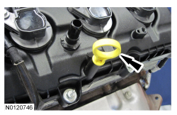
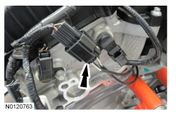
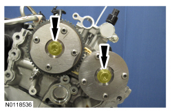
NOTE: Removal of the VCT oil control solenoid will aid in the removal of the primary timing chain.
NOTE: A slight twisting motion will aid in the removal of the VCT oil control solenoid.
NOTE: Keep the VCT oil control solenoid clean of dirt and debris.
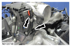
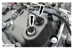
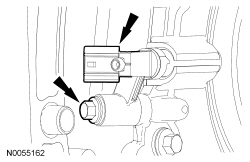
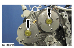
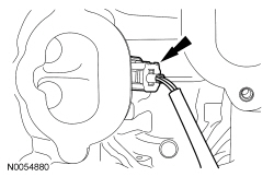
Remove the bolt and the LH intake VCT oil control solenoid.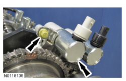
NOTE: Removal of the VCT oil control solenoid will aid in the removal of the primary timing chain.
NOTE: A slight twisting motion will aid in the removal of the VCT oil control solenoid.
NOTE: Keep the VCT oil control solenoid clean of dirt and debris.
Remove the bolt and the RH intake VCT oil control solenoid.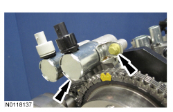
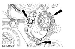
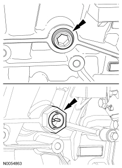
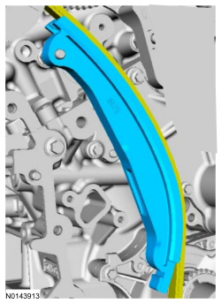
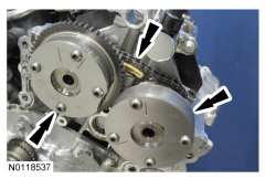
NOTICE: Do not use power tools to remove the bolt or damage to the LH primary timing chain guide may occur.
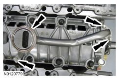
Remove the bolt and the upper LH primary timing chain guide.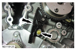
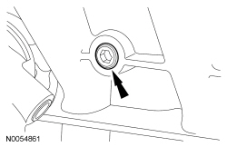
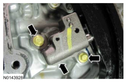
NOTE: The 2 VCT oil control solenoids are removed for clarity.
NOTE: The Secondary Chain Hold Down is inserted through a hole in the top of the mega cap.
Compress the LH secondary timing chain tensioner and install the Secondary Chain Hold Down in the hole on the rear of the secondary timing chain tensioner guide and let it hold against the mega cap to retain the tensioner in the collapsed position.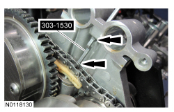
NOTE: The 2 VCT oil control solenoids are removed for clarity.
NOTE: The Secondary Chain Hold Down is inserted through a hole in the top of the mega cap.
Compress the RH secondary timing chain tensioner and install the Secondary Chain Hold Down in the hole on the rear of the secondary timing chain tensioner guide and let it hold against the mega cap to retain the tensioner in the collapsed position.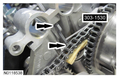
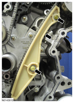
NOTICE: Do not use power tools to remove the bolt or damage to the RH primary timing chain guide may occur.
Remove the bolt and the RH primary timing chain guide.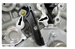
NOTE: When the Camshaft Holding Tool is removed, valve spring pressure may rotate the LH camshafts approximately 3 degrees to a neutral position.
Remove the Camshaft Holding Tool from the LH camshafts.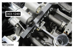
NOTICE: The camshafts must remain in the neutral position during removal or engine damage may occur.
Verify the LH camshafts are in the neutral position.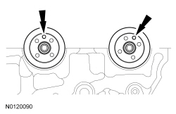
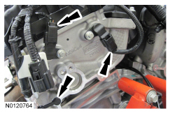
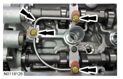
NOTE: Cylinder head camshaft bearing caps are numbered to verify that they are assembled in their original positions.
NOTE: Mark the exhaust and intake camshafts for installation into their original locations.
Remove the 12 bolts, 6 camshaft caps, mega cap and the LH camshafts.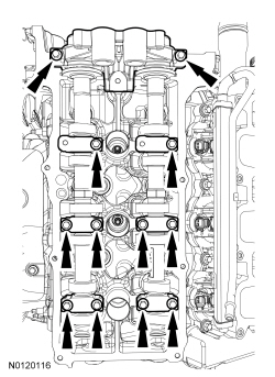
NOTE: When the Camshaft Holding Tool is removed, valve spring pressure may rotate the RH camshafts approximately 3 degrees to a neutral position.
Remove the Camshaft Holding Tool from the RH camshafts.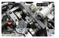
NOTICE: The camshafts must remain in the neutral position during removal or engine damage may occur.
Rotate the RH camshafts counterclockwise to the neutral position.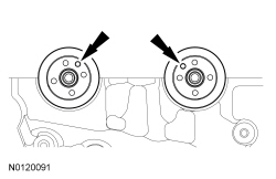
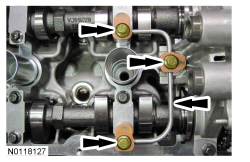
NOTE: Cylinder head camshaft bearing caps are numbered to verify that they are assembled in their original positions.
NOTE: Mark the exhaust and intake camshafts for installation into their original locations.
Remove the 12 bolts, 6 camshaft caps, mega cap and the RH camshafts.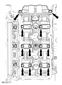
NOTE: If the components are to be reinstalled, they must be installed in the same positions. Mark the components for installation into their original locations.
NOTE: LH shown, RH similar.
Remove the valve tappets from the cylinder heads.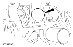
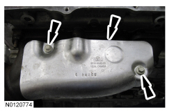
NOTICE: If the engine is repaired or replaced because of upper engine failure, typically including valve or piston damage, check the intake manifold for metal debris. If metal debris is found, install a new intake manifold. Failure to follow these instructions can result in engine damage.
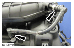
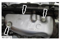
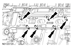
Remove the 10 bolts and the lower intake manifold.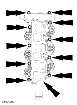
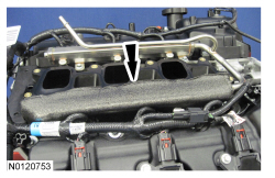
NOTE: LH shown, RH similar.
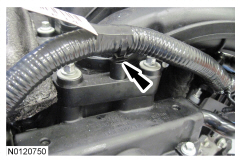
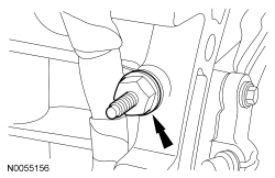
Remove and discard the M6 bolt from each cylinder head.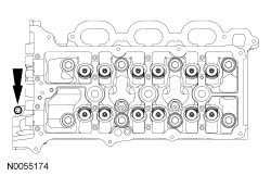
NOTICE: Place clean, lint-free shop towels over exposed engine cavities. Carefully remove the towels so foreign material is not dropped into the engine. Any foreign material (including any material created while cleaning gasket surfaces) that enters the oil passages or the oil pan, may cause engine failure.
NOTICE: Aluminum surfaces are soft and may be scratched easily. Never place the cylinder head gasket surface, unprotected, on a bench surface.
NOTE: The cylinder head bolts must be discarded and new bolts must be installed. They are a tighten-to-yield design and cannot be reused.
NOTE: LH shown, RH similar.
Remove and discard the 8 bolts from each cylinder head.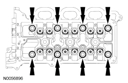
NOTICE: Do not use metal scrapers, wire brushes, power abrasive discs or other abrasive means to clean the sealing surfaces. These tools cause scratches and gouges that make leak paths. Use a plastic scraping tool to remove all traces of the head gasket.
NOTE: Observe all warnings or cautions and follow all application directions contained on the packaging of the silicone gasket remover and the metal surface prep.
NOTE: If there is no residual gasket material present, metal surface prep can be used to clean and prepare the surfaces.
Clean the cylinder head-to-cylinder block mating surfaces of both the cylinder heads and the cylinder block in the following sequence.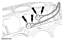
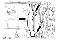
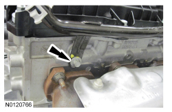
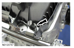
NOTE: RH shown, LH similar.
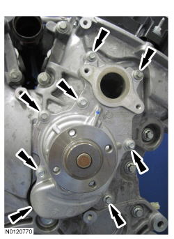
Using a suitable pry tool, locate the 2 pry pads at the LH and RH side of the oil pan and pry the oil pan loose and remove.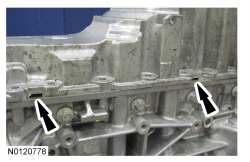
NOTICE: Only use a 3M™ Roloc® Bristle Disk (2-in white, part number 07528) to clean the engine front cover and oil pan. Do not use metal scrapers, wire brushes or any other power abrasive disk to clean the engine front cover and oil pan. These tools cause scratches and gouges that make leak paths.
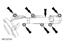
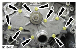
Clean the engine front cover and oil pan using a 3M™ Roloc® Bristle Disk (2-in white, part number 07528) in a suitable tool turning at the recommended speed of 15,000 rpm.NOTE: The main bearing cap support brace bolts must be discarded and new bolts must be installed. They are a tighten-to-yield design and cannot be reused.
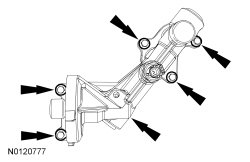
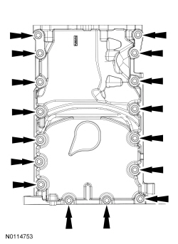
Remove the bolts in the sequence shown.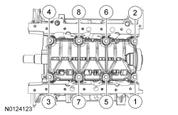
NOTE: The connecting rod cap bolts are a tighten-to-yield design. The original connecting rod cap bolts will be used when measuring the connecting rod large end bore during assembly. The connecting rod cap bolts will be discarded after measurement.
NOTE: Clearly mark the position and orientation of the connecting rods, connecting rod caps and connecting rod bearings for reassembly.
Remove the connecting rod cap bolts and cap.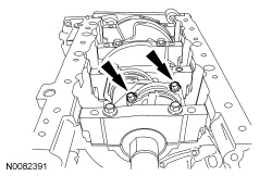
NOTICE: Do not scratch the cylinder walls or crankshaft journals with the connecting rod.
Remove the piston/rod assembly from the engine block.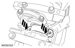
NOTE: The 8 main bearing cap side bolts must be discarded and new bolts must be installed. They are a tighten-to-yield design and cannot be reused.
NOTE: Clearly mark the position and orientation of the main bearing caps for reassembly.
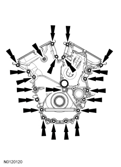
Remove the 8 main bearing cap side bolts in the sequence shown.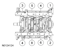
NOTE: The 8 main bearing cap bolts must be discarded and new bolts must be installed. They are a tighten-to-yield design and cannot be reused.
NOTE: Clearly mark the position and orientation of the main bearing caps for reassembly.
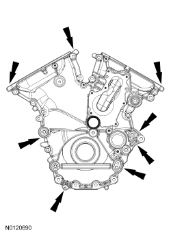
Remove the 8 main bearing cap bolts in the sequence shown.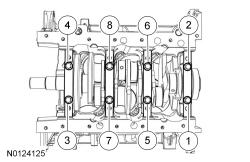
NOTE: If the main bearings are being reused, mark them for correct position and orientation for reassembly.
NOTE: Note the position of the thrust washer on the outside of the No. 4 rear main bearing cap.
Remove the 4 main bearing caps.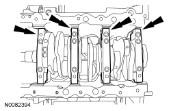
NOTE: Note the position of the 2 thrust washers on the inside and outside of the rear main bearing bulkhead.
Remove the crankshaft.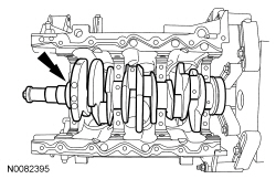
NOTE: Inside shown, outside similar.
Remove the 2 crankshaft thrust bearings from the rear main bearing bulkhead.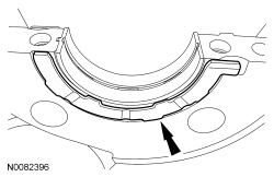
NOTE: If the main bearings are being reused, mark them for correct position and orientation for reassembly.
Remove the 4 crankshaft main bearings from the cylinder block.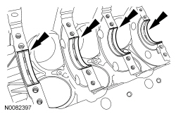
NOTE: If the main bearings are being reused, mark them for correct position and orientation for reassembly.
Remove the 4 crankshaft main bearings from the main bearing caps.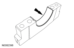
NOTICE: Do not use wire brushes, power abrasive discs or 3M™ Roloc® Bristle Disk (2-in white, part number 07528) to clean the sealing surfaces. These tools cause scratches and gouges that make leak paths. They also cause contamination that causes premature engine failure. Remove all traces of the gasket.
Clean the sealing surfaces of the cylinder heads, the cylinder block and the oil pan in the following sequence.