303-300 (T87C-6565-A)

303-350 (T89P-6565-A)

303-1249

303-470 (T94P-6510-CH)
SECTION 303-01A: Engine — 3.7L
| 2014 Mustang Workshop Manual
|
DISASSEMBLY AND ASSEMBLY OF SUBASSEMBLIES
| Procedure revision date: 01/07/2013
|
| Compressor, Valve Spring
303-300 (T87C-6565-A) |
| Compressor, Valve Spring
303-350 (T89P-6565-A) |
| Compressor, Valve Spring
303-1249 |
| Installer, Valve Stem Oil Seal
303-470 (T94P-6510-CH) |
| Item | Specification |
|---|---|
| Motorcraft® SAE 5W-20 Premium Synthetic Blend Motor Oil (US); Motorcraft® SAE 5W-20 Super Premium Motor Oil (Canada)
XO-5W20-QSP (US); CXO-5W20-LSP12 (Canada) | WSS-M2C945-A |
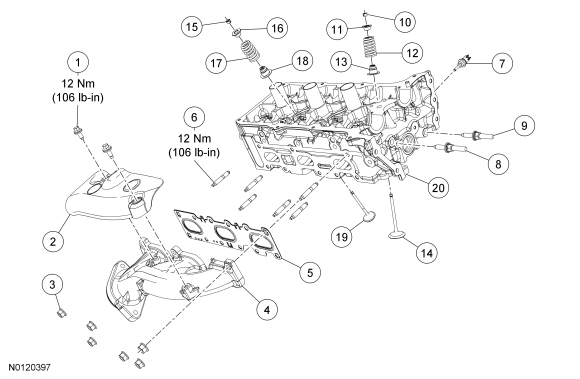
NOTE: RH cylinder head shown, LH cylinder head similar.
| Item | Part Number | Description |
|---|---|---|
| 1 | W714133 | RH exhaust manifold heat shield bolt (2 required) |
| 2 | 9A462 | RH exhaust manifold heat shield |
| 3 | W701706 | RH exhaust manifold nut (6 required) |
| 4 | 9430 | RH exhaust manifold |
| 5 | 9448 | RH exhaust manifold gasket |
| 6 | W712244 | RH exhaust manifold stud (6 required) |
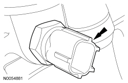
| 7 | 6G004 | Cylinder Head Temperature (CHT) sensor |
| 8 | W714090 | Timing chain tensioner arm pin |
| 9 | W714090 | Timing chain guide pin |
| 10 | 6518 | Intake valve spring retainer key (12 required) |
| 11 | 6514 | Intake valve spring retainer (6 required) |
| 12 | 6513 | Intake valve spring (6 required) |
| 13 | 6571 | Intake valve stem seal (6 required) |
| 14 | 6505 | Intake valve (6 required) |
| 15 | 6518 | Exhaust valve spring retainer key (12 required) |
| 16 | 6514 | Exhaust valve spring retainer (6 required) |
| 17 | 6513 | Exhaust valve spring (6 required) |
| 18 | 6571 | Exhaust valve stem seal (6 required) |
| 19 | 6507 | Exhaust valve (6 required) |
| 20 | 6049 | RH cylinder head |
Disassembly
All cylinder heads
NOTE: If the components are to be reinstalled, they must be installed in the same positions. Mark the components for installation into their original locations.
Using the Valve Spring Compressors, remove the keys, retainer and spring.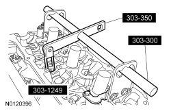
RH cylinder head
Assembly
All cylinder heads
NOTE: If the components are to being reinstalled, they must be installed into their original location.
NOTE: Lubricate the valve stem and valve stem seal with clean engine oil prior to installation.
Using the Valve Stem Oil Seal Installer, install a new valve stem seal.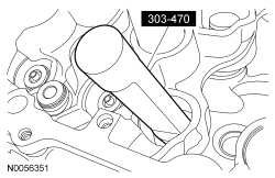
RH cylinder head
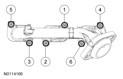
NOTICE: Failure to tighten the exhaust manifold nuts to specification a second time will cause the exhaust manifold to develop an exhaust leak.
Using a new gasket, install the RH exhaust manifold and 6 new nuts. Tighten in 2 stages in the sequence shown: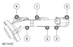
LH cylinder head
NOTICE: Failure to tighten the exhaust manifold nuts to specification a second time will cause the exhaust manifold to develop an exhaust leak.
Using a new gasket, install the LH exhaust manifold and 6 new nuts. Tighten in 2 stages in the sequence shown: