SECTION 303-01A: Engine — 3.7L
| 2014 Mustang Workshop Manual
|
ASSEMBLY
| Procedure revision date: 04/11/2013
|
Engine
Special Tool(s)
 | Compressor, Piston Ring
303-D032 (D81L-6002-C)
|
 | Dial Indicator Gauge with Holding Fixture
100-002 (TOOL-4201-C)
|
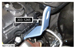
 | Eye, Engine Lift
303-1245
|
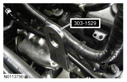
 | Lift Eye, RH Front
303-1529
|
 | Handle
205-153 (T80T-4000-W)
|
 | Hold Down, Secondary Chain
303-1530
|
 | Installer, Differential Bearing Cone
205-142 (T80T-4000-J)
|
 | Installer, Spindle Bearing
205-149 (T80T-4000-R)
|
 | 2,200# Floor Crane, Fold Away
300-OTC1819E
|
 | Installer, Crankshaft Vibration Damper
303-102 (T74P-6316-B)
|
 | Installer, Front Cover Oil Seal
303-335
|
 | Installer, Front Crankshaft Seal
303-1251
|
 | Installer, VCT Spark Plug Tube Seal
303-1247/2
|
 | Spreader Bar
303-D089 (D93P-6001-A3) or equivalent
|
 | Strap Wrench
303-D055 (D85L-6000-A)
|
 | Tool, Camshaft Holding
303-1248
|
Material
| Item
| Specification
|
|---|
Motorcraft® High Performance Engine RTV Silicone
TA-357
| WSE-M4G323-A6
|
Motorcraft® Metal Surface Prep
ZC-31-A
| —
|
Motorcraft® SAE 5W-20 Premium Synthetic Blend Motor Oil (US); Motorcraft® SAE 5W-20 Super Premium Motor Oil (Canada)
XO-5W20-QSP (US); CXO-5W20-LSP12 (Canada)
| WSS-M2C945-A
|
Motorcraft® Orange Antifreeze/Coolant Concentrated
VC-3-B (US); CVC-3-B2 (Canada)
| WSS-M97B44-D
|
Motorcraft® Orange Antifreeze/Coolant Prediluted
VC-3DIL-B (US); CVC-3DIL-B (Canada)
| WSS-M97B44-D2
|
Motorcraft® Silicone Gasket Remover
ZC-30
| —
|
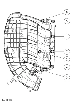
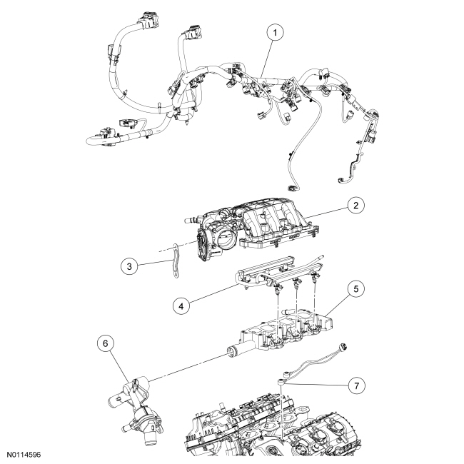
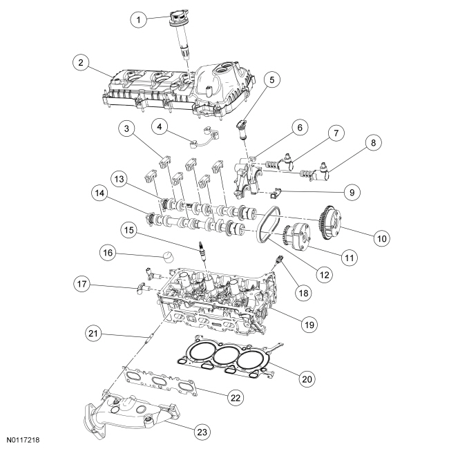
Engine Upper
| Item
| Part Number
| Description
| | 1
| 12A581
| Engine control harness
|
| 2
| 9424
| Upper intake manifold
|
| 3
| 9J444
| Upper intake manifold support bracket
|
| 4
| 9F797
| Fuel rail
|
| 5
| 9424
| Lower intake manifold
|
| 6
| 8A586
| Thermostat housing
|
| 7
| 12A699
| Knock Sensor (KS)
|
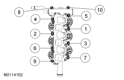
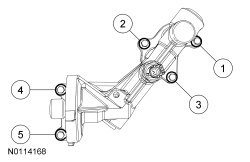
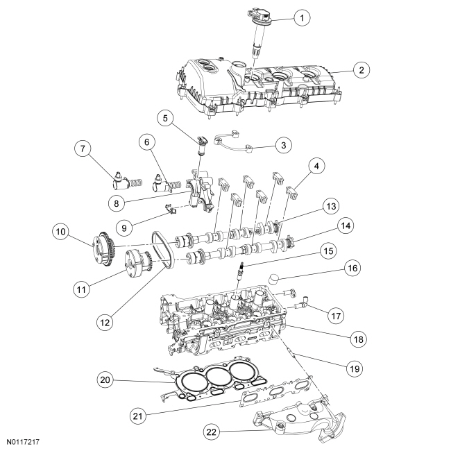
Engine Upper — LH Cylinder Head
| Item
| Part Number
| Description
| | 1
| 12029
| Ignition coil-on-plug (3 required)
|
| 2
| 6582
| LH valve cover
|
| 3
| 6K602
| Valve train oil feed tube
|
| 4
| 6A258
| LH camshaft cap (6 required)
|
| 5
| 6K254
| LH secondary timing chain tensioner
|
| 6
| 6M280
| Intake camshaft Variable Camshaft Timing (VCT) oil control solenoid
|
| 7
| 6M280
| Exhaust camshaft
oil control solenoid
|
| 8
| 6B280
| Camshaft mega cap
|
| 9
| 6K297
| LH secondary tensioner shoe
|
| 10
| 6256
| Intake camshaft
assembly
|
| 11
| 6C525
| Exhaust camshaft
assembly
|
| 12
| 6268
| LH secondary timing chain
|
| 13
| 6250
| LH intake camshaft
|
| 14
| 6250
| LH exhaust camshaft
|
| 15
| 12405
| Spark plug (3 required)
|
| 16
| 6500
| Valve tappet (32 required)
|
| 17
| 6B288
| LH cylinder head Camshaft Position (CMP) sensor (2 required)
|
| 18
| 6049
| LH cylinder head
|
| 19
| W712244
| LH exhaust manifold stud (6 required)
|
| 20
| 6051
| LH cylinder head gasket
|
| 21
| 9448
| LH exhaust manifold gasket
|
| 22
| 9431
| LH exhaust manifold
|
Engine Upper — RH Cylinder Head
| Item
| Part Number
| Description
| | 1
| 12029
| Ignition coil-on-plug (3 required)
|
| 2
| 6582
| RH valve cover
|
| 3
| 6A258
| RH camshaft cap (6 required)
|
| 4
| 6K602
| Valve train oil feed tube
|
| 5
| 6K254
| RH secondary timing chain tensioner
|
| 6
| 6B280
| Camshaft mega cap
|
| 7
| 6M280
| Intake camshaft Variable Camshaft Timing (VCT) oil control solenoid
|
| 8
| 6M280
| Exhaust camshaft
oil control solenoid
|
| 9
| 6K297
| RH secondary tensioner shoe
|
| 10
| 6256
| Intake camshaft
assembly
|
| 11
| 6C525
| Exhaust camshaft
assembly
|
| 12
| 6268
| RH secondary timing chain
|
| 13
| 6250
| RH intake camshaft
|
| 14
| 6250
| RH exhaust camshaft
|
| 15
| 12405
| Spark plug (3 required)
|
| 16
| 6500
| Valve tappet (32 required)
|
| 17
| 6B288
| RH cylinder head Camshaft Position (CMP) sensor (2 required)
|
| 18
| 6G004
| Cylinder Head Temperature (CHT) sensor
|
| 19
| 6049
| RH cylinder head
|
| 20
| 6051
| RH cylinder head gasket
|
| 21
| W712244
| RH exhaust manifold stud (6 required)
|
| 22
| 9448
| RH exhaust manifold gasket
|
| 23
| 9430
| RH exhaust manifold
|
Engine Front
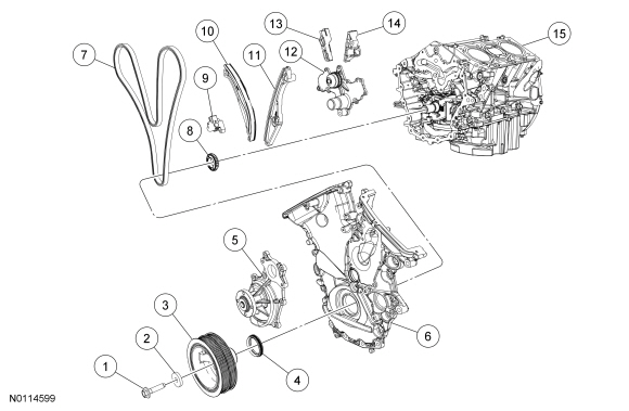
| Item
| Part Number
| Description
| | 1
| 6A340
| Crankshaft pulley bolt
|
| 2
| 6378
| Crankshaft pulley washer
|
| 3
| 6312
| Crankshaft pulley
|
| 4
| 6700
| Crankshaft front seal
|
| 5
| 8501
| Coolant pump
|
| 6
| 6019
| Engine front cover
|
| 7
| 6268
| Timing chain
|
| 8
| 6306
| Crankshaft timing sprocket
|
| 9
| 6K254
| Primary timing chain tensioner
|
| 10
| 6K255
| Primary timing chain tensioner arm
|
| 11
| 6B274
| LH lower primary timing chain guide
|
| 12
| 8501
| Channel cover plate
|
| 13
| 6M256
| RH primary timing chain guide
|
| 14
| 6K297
| LH upper primary timing chain guide
|
| 15
| 6010
| Cylinder block
|
Lower Engine Block (View 1)

| Item
| Part Number
| Description
| | 1
| 6600
| Oil pump
|
| 2
| 6625
| Oil pump screen and pickup tube O-ring seal
|
| 3
| 6622
| Oil pump screen and pickup tube
|
| 4
| 6675
| Oil pan
|
| 5
| 6731
| Engine oil filter
|
| 6
| 6881
| Oil filter adapter
|
| 7
| 9278
| Engine Oil Pressure (EOP) switch
|
| 8
| 6C315
| Crankshaft Position (CKP) sensor
|
| 9
| 6477
| Flywheel
|
| 10
| 6K301
| Crankshaft rear seal retainer
|
| 11
| 12A227
| Crankshaft sensor ring
|
| 12
| 6375
| Flexplate
|
| 13
| 6010
| Cylinder block
|
Lower Engine Block (View 2)
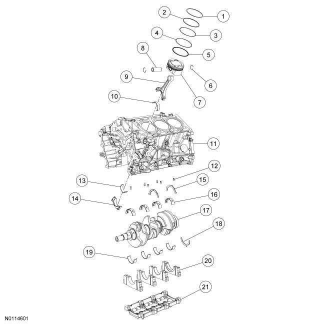
| Item
| Part Number
| Description
| | 1
| —
| Piston compression upper ring (part of 6148) (6 required)
|
| 2
| —
| Piston compression lower ring (part of 6148) (6 required)
|
| 3
| —
| Piston oil control upper segment ring (part of 6148) (6 required)
|
| 4
| —
| Piston oil control spacer (part of 6148) (6 required)
|
| 5
| —
| Piston oil control lower segment ring (part of 6148) (6 required)
|
| 6
| 6140
| Piston pin retainer (12 required)
|
| 7
| 6110
| Piston (6 required)
|
| 8
| 6135
| Piston pin (6 required)
|
| 9
| 6200
| Connecting rod (6 required)
|
| 10
| 6211
| Connecting rod upper bearing (6 required)
|
| 11
| 6010
| Cylinder block
|
| 12
| —
| Piston oil cool valve (6 required) (part of 6010)
|
| 13
| 6211
| Connecting rod lower bearing (6 required)
|
| 14
| 6200
| Connecting rod cap (6 required)
|
| 15
| 6A341
| Crankshaft upper thrust washer (2 required)
|
| 16
| 6D309
| Cylinder block crankshaft main bearing (4 required)
|
| 17
| 6303
| Crankshaft
|
| 18
| 6K302
| Crankshaft lower thrust washer
|
| 19
| 6D309
| Lower crankshaft main bearing (4 required)
|
| 20
| 6325
| Lower crankshaft main bearing cap (4 required)
|
| 21
| 6C364
| Main bearing cap support brace
|
NOTICE:
During engine repair procedures, cleanliness is extremely important. Any foreign material, including any material created while cleaning gasket surfaces that enters the oil passages, coolant passages or the oil pan, may cause engine failure.
NOTE:
Assembly of the engine requires various inspections/measurements of the engine components (engine block, crankshaft, connecting rods and pistons.). These inspections/measurements will aid in determining if the engine components will require replacement. For additional information, refer to
Section 303-00
.
All vehicles
NOTE:
This procedure is for selecting bearings using a new crankshaft.
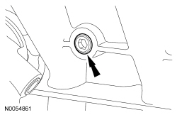
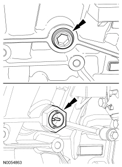
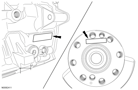
Select the crankshaft main bearings for each crankshaft journal.
- Read the code on the crankshaft flange.
- Read the code on the cylinder block face.
- The first letter after the first asterisk makes up the code for main No. 1 and the next letter for main No. 2. The first letter after the second asterisk makes up the code for main No. 3 and the last letter for main No. 4.
NOTE:
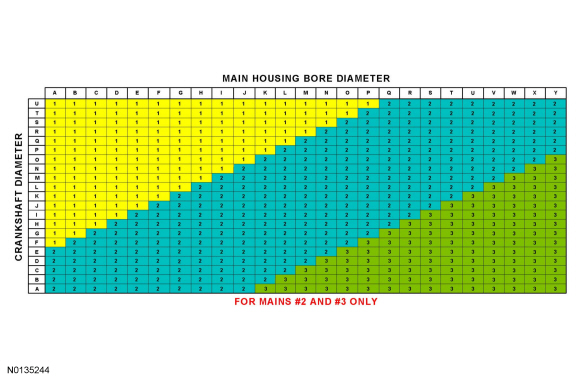
This chart is for selecting main bearings 1 and 4 only, the remaining bearings will be selected using a different chart in the next step.
Using the data recorded earlier and the Bearing Select Fit Chart, Standard Bearings, determine the required bearing grade for main bearings 1 and 4.
- Read the first letter of the engine block main bearing code and the first letter of the crankshaft main bearing code.
- Read down the column below the engine block main bearing code letter and across the row next to the crankshaft main bearing code letter, until the 2 intersect. This is the required bearing grade(s) for the No. 1 crankshaft main bearing.
- As an example, if the engine block code letter is "F" and the crankshaft code letter is "P", the correct bearing grade for this main bearing is a "1" for the upper bearing and a "2" for the lower bearing.
- Repeat the above steps using the fourth letter of the block and crankshaft codes to select the No. 4 bearing.

NOTE:
This chart is for selecting main bearings 2 and 3 only.
Using the data recorded earlier and the Bearing Select Fit Chart, Standard Bearings, determine the required bearing grade for main bearings 2 and 3.
- Read the second letter of the engine block main bearing code and the second letter of the crankshaft main bearing code.
- Read down the column below the engine block main bearing code letter and across the row next to the crankshaft main bearing code letter, until the 2 intersect. This is the required bearing grade for the No. 2 crankshaft main bearing.
- As an example, if the engine block code letter is "F" and the crankshaft code letter is "P", the correct bearing grade for this main bearing is "1".
- Repeat the above steps using the third letter of the block and crankshaft codes to select the No. 3.
NOTICE:
The rod cap installation must keep the same orientation as marked during disassembly or engine damage may occur.
Using the original connecting rod cap bolts, install the connecting rod caps and bolts.
- Tighten the bolts in 3 stages.
- Stage 1: Tighten to 23 Nm (17 lb-ft).
- Stage 2: Tighten to 43 Nm (32 lb-ft).
- Stage 3: Tighten an additional 90 degrees.
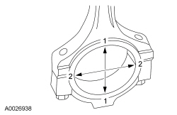
- Measure the connecting rod large end bore in 2 directions.
- Remove the bolts and the rod cap.
- Discard the connecting rod cap bolts.
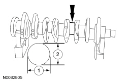
- Measure each of the crankshaft connecting rod bearing journal diameters in at least 2 directions.
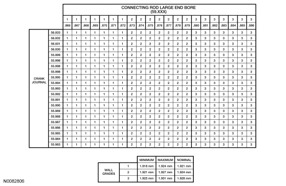
- Using the chart, select the correct connecting rod bearings for each crankshaft connecting rod journal.
NOTE:
Before assembling the cylinder block, all sealing surfaces must be free of chips, dirt, paint and foreign material. Also, make sure the coolant and oil passages are clear.
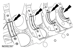
Lubricate the upper crankshaft main bearings with clean engine oil and install the 4 crankshaft main bearings in the cylinder block.
NOTE:
Do not install the upper thrust bearings until the crankshaft is installed.
NOTE:
Lubricate the thrust surfaces of the crankshaft with clean engine oil.
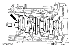
Install the crankshaft onto the upper main bearings.
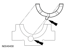
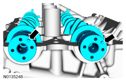
NOTE:
Make sure the side of the thrust washer, with the wide oil grooves, faces the crankshaft thrust surface.
Push the crankshaft rearward and install the rear crankshaft upper thrust washer at the back of the No. 4 rear bulkhead.
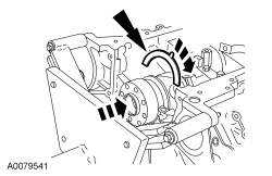
NOTE:
Make sure the side of the thrust washer, with the wide oil grooves, faces the crankshaft thrust surface.
Push the crankshaft forward and install the front crankshaft upper thrust washer at the front of the No. 4 rear bulkhead.
- Lubricate the crankshaft lower main bearings with clean engine oil and install them into the main bearing caps. Visually check seating and squareness of the bearings to make sure of proper seating in caps.
- Position the No. 1, No. 2 and No. 3 main bearing caps on the cylinder block and, keeping the caps as square as possible, alternately draw the caps down evenly using the new bolts until the main bearing caps are seated.
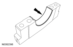
NOTE:
Make sure the side of the thrust washer, with the wide oil grooves, faces the crankshaft thrust surface.
NOTE:
To aid in assembly, apply petroleum jelly to the back of the crankshaft thrust washer.
Install the lower crankshaft thrust washer to the back side of the No. 4 rear main bearing cap, with the tab aligned with the cutout in the main bearing cap.
- Position main bearing cap No. 4 on the cylinder block and keeping the cap as square as possible, alternately draw the cap down evenly using the new bolts until the main bearing cap is seated.
- Loosen the No. 4 main bearing cap bolts.
NOTE:
While tightening the main bearing vertical bolts, push the crankshaft forward and the No. 4 main bearing cap rearward to seat the crankshaft thrust washers.
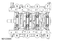
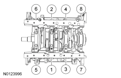
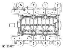
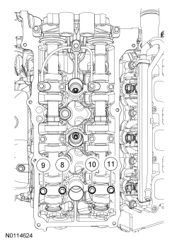
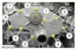
Tighten the main bearing bolts in the sequence shown in 2 stages.
- Stage 1: Tighten fasteners 1 through 8 to 33 Nm (24 lb-ft).
- Stage 2: Tighten fasteners 1 through 8 an additional 135 degrees.
- Install the new 8 main bearing cap side bolts. Tighten in the sequence shown in 2 stages.
- Stage 1: Tighten fasteners 1 through 8 to 24 Nm (18 lb-ft).
- Stage 2: Tighten fasteners 1 through 8 an additional 180 degrees.
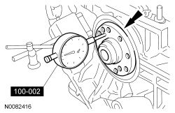
- Using the Dial Indicator Gauge with Holding Fixture, measure crankshaft end play.
- Position the crankshaft to the rear of the cylinder block.
- Zero the Dial Indicator Gauge.
- Move the crankshaft to the front of the cylinder block. Note and record the crankshaft end play.
NOTICE:
The rod cap installation must keep the same orientation as marked during disassembly or engine damage may occur.
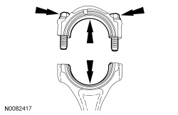
Prepare the connecting rod and cap.
- Insert the new bolts in the rod cap.
- Insert the upper and lower rod bearings into the rod and cap.
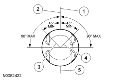
- Before installing the pistons into the cylinder block, verify proper ring gap location.
- Center line of the piston parallel to the wrist pin bore
- Upper compression ring gap location
- Upper oil control segment ring gap location
- Lower oil control segment ring gap location
- Expander ring and lower compression ring gap location
NOTICE:
Be sure not to scratch the cylinder wall or crankshaft journal with the connecting rod. Push the piston down until the connecting rod bearing seats on the crankshaft journal.
NOTE:
The next 3 steps are for all 6 connecting rods, rod caps and pistons. Only 1 connecting rod, rod cap and piston is shown.
NOTE:
Lubricate the pistons, piston rings, connecting rod bearings and the entire cylinder bores with clean engine oil.
NOTE:
Make sure the piston rings are positioned to specifications for installation. For additional information, refer to Disassembly and Assembly of Subassemblies - Piston in this section.
NOTE:
If the piston and/or connecting rod are being installed new, the piston rod orientation marks and the arrow on the top of the dome of the piston should be facing toward the front of the engine block.
NOTE:
If the piston and connecting rod are to be reinstalled, they must be installed in the same orientation as disassembled.
Using the Piston Ring Compressor, install the piston and connecting rod assemblies.
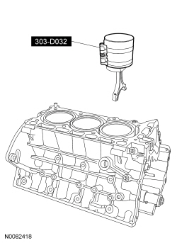
- Seat the connecting rod on the crankshaft journal.
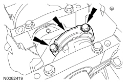
NOTICE:
The rod cap installation must keep the same orientation as marked during disassembly or engine damage may occur.
NOTE:
After installation of each piston, connecting rod, rod cap and bolts, rotate the crankshaft to verify smooth operation.
Install the connecting rod cap and bolts.
- Tighten the bolts in 3 stages.
- Stage 1: Tighten to 23 Nm (17 lb-ft).
- Stage 2: Tighten to 43 Nm (32 lb-ft).
- Stage 3: Tighten an additional 90 degrees.
- Repeat the previous 3 steps until all 6 piston, connecting rod and connecting rod cap assemblies are installed.
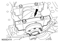
- Install the main bearing cap support brace and the new bolts. Tighten in the sequence shown in 2 steps.
- Stage 1: Tighten fasteners to 20 Nm (177 lb-in).
- Stage 2: Tighten fasteners an additional 180 degrees.
NOTICE:
Failure to use Motorcraft® High Performance Engine RTV Silicone may cause the engine oil to foam excessively and result in serious engine damage.
NOTE:
The crankshaft rear seal retainer must be installed and the bolts tightened within 10 minutes of sealant application.
NOTE:
The stamped steel crankshaft rear seal retainer plate comes with the crankshaft rear seal.
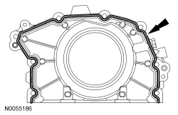
Apply a 3 mm (0.11 in) bead of Motorcraft® High Performance Engine RTV Silicone to the sealing surface of the crankshaft rear seal retainer.
NOTE:
Lubricate the crankshaft rear seal with clean engine oil.
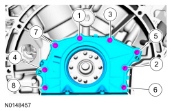
Install the crankshaft rear seal retainer and the 8 bolts.
- Tighten in the sequence shown to 10 Nm (89 lb-in).
- Install the oil pump and the 3 bolts.
- Tighten to 10 Nm (89 lb-in).
- Using a new O-ring seal, install the oil pump screen and pickup tube and the 3 bolts.
- Tighten to 10 Nm (89 lb-in).
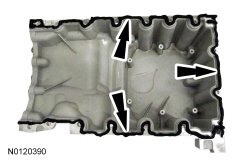
NOTICE:
Failure to use Motorcraft® High Performance Engine RTV Silicone may cause the engine oil to foam excessively and result in serious engine damage.
NOTE:
The oil pan and the 4 specified bolts must be installed and the oil pan aligned to the cylinder block within 4 minutes of sealant application. Final tightening of the oil pan bolts must be carried out within 60 minutes of sealant application.
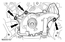
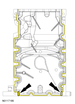
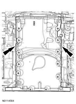
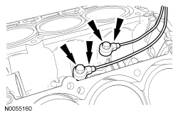
Apply a 3 mm (0.11 in) bead of Motorcraft® High Performance Engine RTV Silicone to the sealing surface of the oil pan-to-engine block mating surface.
- Apply a 5.5 mm (0.21 in) bead of Motorcraft® High Performance Engine RTV Silicone to the 2 crankshaft seal retainer plate-to-cylinder block joint areas on the sealing surface of the oil pan.
NOTE:
The oil pan and the 4 specified bolts must be installed within 4 minutes of the start of sealant application.
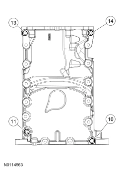
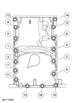
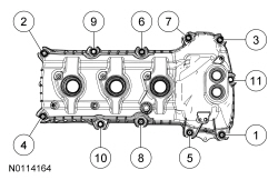
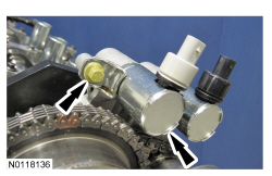
Install the oil pan and bolts 10, 11, 13 and 14 finger tight.
- Laterally align the oil pan to the block. Make sure the oil pan is flush with the block at these 2 points.
- Tighten bolts 10, 11, 13 and 14 in the sequence shown to 3 Nm (27 lb-in).
- Install the remaining oil pan bolts and tighten in the sequence shown.
- Tighten bolts 1-9 and 11-14 to 20 Nm (177 lb-in), then rotate an additional 45 degrees.
- Tighten bolts 15 and 16 to 10 Nm (89 lb-in), then rotate an additional 45 degrees.
- Tighten bolt 10 to 20 Nm (177 lb-in), then rotate an additional 90 degrees.
- Install the Knock Sensor (KS) and the 2 bolts.
- Tighten to 20 Nm (177 lb-in).
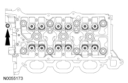
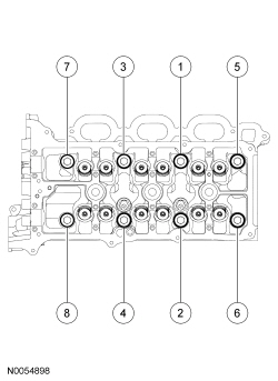
- Install a new gasket, the RH cylinder head and 8 new bolts. Tighten in the sequence shown in 5 stages:
- Stage 1: Tighten to 20 Nm (177 lb-in).
- Stage 2: Tighten to 35 Nm (26 lb-ft).
- Stage 3: Tighten 90 degrees.
- Stage 4: Tighten 90 degrees.
- Stage 5: Tighten 45 degrees.
- Install the M6 bolt.
- Tighten to 10 Nm (89 lb-in).
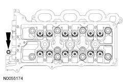
- Install a new gasket, the LH cylinder head and 8 new bolts. Tighten in the sequence shown in 5 stages:
- Stage 1: Tighten to 20 Nm (177 lb-in).
- Stage 2: Tighten to 35 Nm (26 lb-ft).
- Stage 3: Tighten 90 degrees.
- Stage 4: Tighten 90 degrees.
- Stage 5: Tighten 45 degrees.
- Install the M6 bolt.
- Tighten to 10 Nm (89 lb-in).
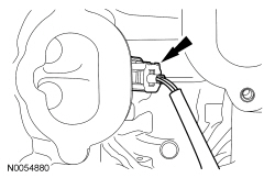
- Install and connect the Cylinder Head Temperature (CHT) sensor jumper harness.
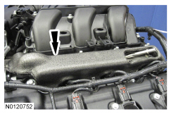
NOTICE:
If the engine is repaired or replaced because of upper engine failure, typically including valve or piston damage, check the intake manifold for metal debris. If metal debris if found, install a new intake manifold. Failure to follow these instructions can result in engine damage.
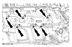
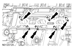
Using new lower intake manifold gaskets, install the lower intake manifold and the 10 bolts and tighten in the sequence shown.
- Tighten to 10 Nm (89 lb-in).
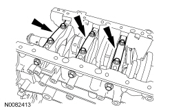
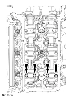
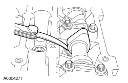
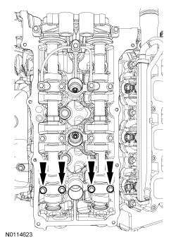
NOTE:
The valve tappets must be installed in their original positions.
NOTE:
Coat the valve tappets with clean engine oil prior to installation.
NOTE:
LH shown, RH similar.
Install the valve tappets.
NOTICE:
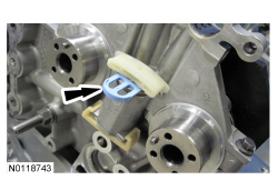
The crankshaft must remain in the freewheeling position (crankshaft dowel pin at 9 o'clock) until after the camshafts are installed and the valve clearance is checked/adjusted. Do not turn the crankshaft until instructed to do so. Failure to follow this process will result in severe engine damage.
Position the crankshaft dowel pin in the 9 o'clock position.
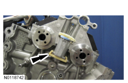
NOTE:
Coat the camshafts with clean engine oil prior to installation.
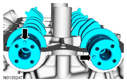
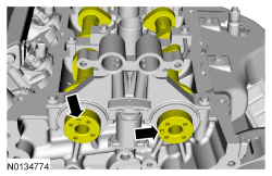
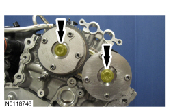
Position the camshafts onto the RH cylinder head in the neutral position as shown.
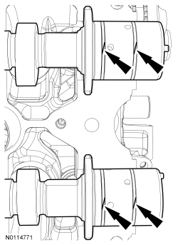
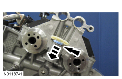
NOTICE:
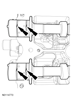
The camshaft seal gaps must be at the 12 o'clock position or damage to the engine may occur.
Position the 4 camshaft seals gaps as shown.
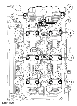
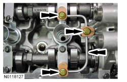
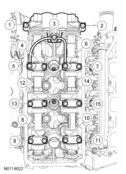
NOTE:
Cylinder head camshaft bearing caps are numbered to verify that they are assembled in their original positions.
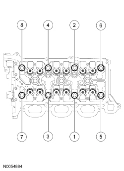
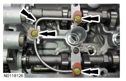
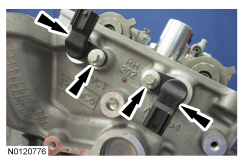
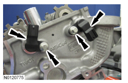
Install the 6 camshaft caps, mega cap, valve train oil tube and the 15 bolts in the sequence shown.
- Tighten to 8 Nm (71 lb-in) then additional 45 degrees.
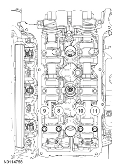
- Loosen the 4 camshaft caps bolts.
- Tighten the 4 camshaft caps bolts in the sequence shown.
- Tighten bolts 8, 9, 10 and 11 to 8 Nm (71 lb-in) then additional 45 degrees.
NOTICE:
If any components are installed new, the engine valve clearance must be checked/adjusted or engine damage may occur.
NOTE:
Use a camshaft sprocket bolt to turn the camshafts.
Using a feeler gauge, confirm that the valve tappet clearances are within specification. If valve tappet clearances are not within specification, the clearance must be adjusted by installing new valve tappet(s) of the correct size. For additional information, refer to
Valve Clearance Check
in this section.
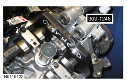
- Remove the 3 bolts and the RH valve train oil tube.
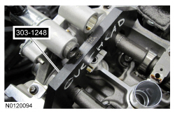
- Rotate the RH camshafts to the Top Dead Center (TDC) position as shown.
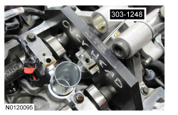
NOTE:
The Camshaft Holding Tool will hold the camshafts in the
position.
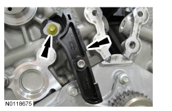
Install the Camshaft Holding Tool onto the flats of the RH camshafts.
NOTE:
Coat the camshafts with clean engine oil prior to installation.
Position the camshafts onto the LH cylinder head in the neutral position as shown.
NOTICE:
The camshaft seal gaps must be at the 12 o'clock position or damage to the engine may occur.
Position the 4 camshaft seals gaps as shown.
NOTE:
Cylinder head camshaft bearing caps are numbered to verify that they are assembled in their original positions.
Install the 6 camshaft caps, mega cap, valve train oil tube and the 15 bolts in the sequence shown.
- Tighten to 8 Nm (71 lb-in) then additional 45 degrees.
- Loosen the 4 camshaft caps bolts.
- Tighten the 4 camshaft caps bolts in the sequence shown.
- Tighten bolts 8, 9, 10 and 11 to 8 Nm (71 lb-in) then additional 45 degrees.
NOTICE:
If any components are installed new, the engine valve clearance must be checked/adjusted or engine damage may occur.
NOTE:
Use a camshaft sprocket bolt to turn the camshafts.
Using a feeler gauge, confirm that the valve tappet clearances are within specification. If valve tappet clearances are not within specification, the clearance must be adjusted by installing new valve tappet(s) of the correct size. For additional information, refer to
Valve Clearance Check
in this section.
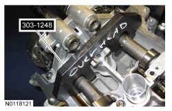
- Remove the 3 bolts and the LH valve train oil tube.
- Rotate the LH camshafts to the
position as shown.
NOTE:
The Camshaft Holding Tool will hold the camshafts in the
position.
Install the Camshaft Holding Tool onto the flats of the LH camshafts.
- Using a new gasket, install the channel cover plate and the 9 bolts. Tighten in the sequence shown in 2 stages:
- Stage 1: Tighten to 10 Nm (89 lb-in).
- Stage 2: Tighten an additional 45 degrees.
- Install the RH primary timing chain guide and the bolt.
- Tighten to 10 Nm (89 lb-in).
Engines with secondary timing chain tensioner removed
NOTICE:
The following steps are only for the replacement of the secondary timing chain tensioners. Do not reuse the secondary timing chain tensioners if removed or damage to the engine may occur.
NOTE:
Apply clean engine oil to the secondary timing chain tensioner O-ring seals and mega cap bore.
NOTE:
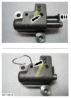
Do not remove the secondary timing chain tensioner shipping clip, until instructed to do so.
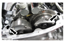
Install the RH secondary timing chain tensioner by pushing it down all the way until a snap is heard and the tensioner is seated all the way down the mega cap bore.
- Install the RH secondary timing chain tensioner shoe.
- Remove and discard the RH secondary timing chain tensioner shipping clip.
- Assemble the RH Variable Camshaft Timing (VCT) assembly, the RH exhaust camshaft sprocket and the RH secondary timing chain.
- Align the colored links with the timing marks.
NOTE:
It may be necessary to rotate the camshafts slightly, to install the RH secondary timing assembly.
Position the 2 RH
assemblies and secondary timing chain onto the camshafts by aligning the holes in the
assemblies with the dowel pins in the camshafts.
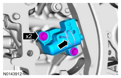
- Install the 2 new RH
bolts and tighten in 4 stages.
- Stage 1: Tighten to 40 Nm (30 lb-ft).
- Stage 2: Loosen one full turn.
- Stage 3: Tighten to 25 Nm (18 lb-ft).
- Stage 4: Tighten an additional 180 degrees.
- Activate the RH secondary timing chain tensioner by pressing down on the secondary tensioner shoe until it bottoms out, let go of the tensioner and it will spring up putting tension on the chain.
NOTE:
A slight twisting motion will aid in the installation of the
oil control solenoid.
NOTE:
Keep the
oil control solenoid clean of dirt and debris.
Install the RH exhaust
oil control solenoid.
- Tighten to 8 Nm (71 lb-in) then an additional 20 degrees.
NOTE:
Apply clean engine oil to the secondary timing chain tensioner O-ring seals and mega cap bore.
NOTE:
Do not remove the secondary timing chain tensioner shipping clip, until instructed to do so.
Install the LH secondary timing chain tensioner by pushing it down all the way until a snap is heard and the tensioner is seated all the way down the mega cap bore.
- Install the LH secondary timing chain tensioner shoe.
- Remove and discard the LH secondary timing chain tensioner shipping clip.
- Assemble the 2 LH
assemblies and the LH secondary timing chain.
- Align the colored links with the timing marks.
NOTE:
It may be necessary to rotate the camshafts slightly, to install the LH secondary timing assembly.
Position the 2 LH
assemblies and secondary timing chain onto the camshafts by aligning the holes in the
assemblies with the dowel pins in the camshafts.
- Install the 2 new LH
bolts and tighten in 4 stages.
- Stage 1: Tighten to 40 Nm (30 lb-ft).
- Stage 2: Loosen one full turn.
- Stage 3: Tighten to 25 Nm (18 lb-ft).
- Stage 4: Tighten an additional 180 degrees.
- Activate the LH secondary timing chain tensioner by pressing down on the secondary tensioner shoe until it bottoms out, let go of the tensioner and it will spring up putting tension on the chain.
NOTE:
A slight twisting motion will aid in the installation of the
oil control solenoid.
NOTE:
Keep the
oil control solenoid clean of dirt and debris.
Install the LH exhaust
oil control solenoid.
- Tighten to 8 Nm (71 lb-in) then an additional 20 degrees.
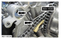
Engines with secondary timing chain tensioner not removed
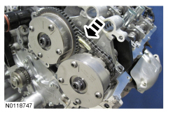
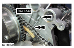
- Compress the RH secondary timing chain tensioner and install the Secondary Chain Hold Down to retain the tensioner in the collapsed position.
- Assemble the RH
assembly, the RH exhaust camshaft sprocket and the RH secondary timing chain.
- Align the colored links with the timing marks.
NOTE:
It may be necessary to rotate the camshafts slightly, to install the RH secondary timing assembly.
Position the 2 RH
assemblies and secondary timing chain onto the camshafts by aligning the holes in the
assemblies with the dowel pins in the camshafts.
- Install the 2 new RH
bolts and tighten in 4 stages.
- Stage 1: Tighten to 40 Nm (30 lb-ft).
- Stage 2: Loosen one full turn.
- Stage 3: Tighten to 25 Nm (18 lb-ft).
- Stage 4: Tighten an additional 180 degrees.
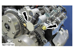
NOTE:
The 2
oil control solenoids are removed for clarity.
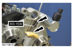
Compress the RH secondary timing chain tensioner and remove the Secondary Chain Hold Down.
- Make sure the secondary timing chain is centered on the timing chain tensioner guides.
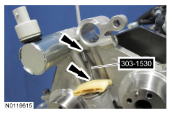
- Compress the LH secondary timing chain tensioner and install the Secondary Chain Hold Down to retain the tensioner in the collapsed position.
- Assemble the 2 LH
assemblies and the LH secondary timing chain.
- Align the colored links with the timing marks.
NOTE:
It may be necessary to rotate the camshafts slightly, to install the LH secondary timing assembly.
Position the 2 LH
assemblies and secondary timing chain onto the camshafts by aligning the holes in the
assemblies with the dowel pins in the camshafts.
- Install the 2 new LH
bolts and tighten in 4 stages.
- Stage 1: Tighten to 40 Nm (30 lb-ft).
- Stage 2: Loosen one full turn.
- Stage 3: Tighten to 25 Nm (18 lb-ft).
- Stage 4: Tighten an additional 180 degrees.
NOTE:
The 2
oil control solenoids are removed for clarity.
Compress the LH secondary timing chain tensioner and remove the Secondary Chain Hold Down.
- Make sure the secondary timing chain is centered on the timing chain tensioner guides.
All engines
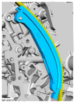
- Install the upper LH primary timing chain guide and the bolt.
- Tighten to 10 Nm (89 lb-in).
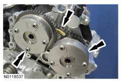
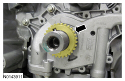
- Rotate the crankshaft clockwise to the
position (crankshaft dowel pin at 11 o'clock).
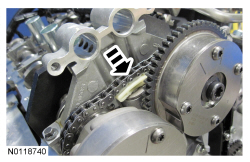
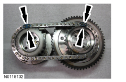
- Install the crankshaft timing chain sprocket with timing dot mark out.
NOTE:
It may be necessary to rotate the camshafts slightly, to align the timing marks.
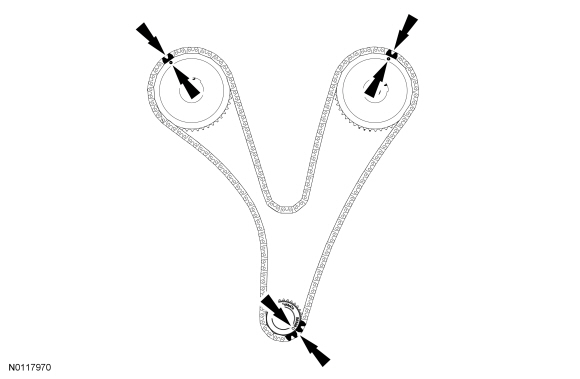
Install the primary timing chain with the colored links aligned with the timing marks on the
assemblies and the crankshaft sprocket.
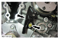
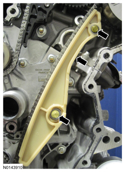
- Install the lower LH primary timing chain guide and the 2 bolts.
- Tighten to 10 Nm (89 lb-in).
- Install the primary timing chain tensioner arm.
- Reset the primary timing chain tensioner.
- Release the ratchet detent.
- Using a soft-jawed vise, compress the ratchet plunger.
- Align the hole in the ratchet plunger with the hole in the tensioner housing.
- Install a suitable lockpin.
NOTE:
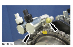
It may be necessary to rotate the camshafts slightly to remove slack from the timing chain to install the tensioner.
Install the primary tensioner and the 2 bolts.
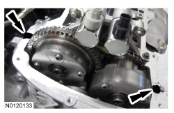
- Tighten to 10 Nm (89 lb-in).
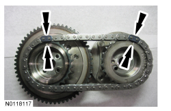
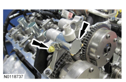
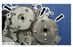
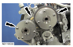
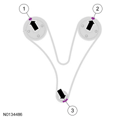
- As a post-check, verify correct alignment of all timing marks.
- There is 48 links in between the RH intake
assembly colored link (1) and the LH intake
assembly colored link (2).
- There is 35 links in between LH intake
assembly colored link (2) and the 2 crankshaft sprocket links (3).
NOTICE:
Do not use excessive force when installing the Variable Camshaft Timing (VCT) oil control solenoid. Damage to the mega cap could cause the cylinder head to be inoperable. If difficult to install the
oil control solenoid, inspect the bore and
oil control solenoid to ensure there are no burrs, sharp edges or contaminants present on the mating surface. Only clean the external surfaces as necessary.
NOTE:
A slight twisting motion will aid in the installation of the
oil control solenoid.
NOTE:
Keep the
oil control solenoid clean of dirt and debris.
Install the LH intake
oil control solenoid and the bolt.
- Tighten to 8 Nm (71 lb-in) then an additional 20 degrees.
NOTICE:
Do not use excessive force when installing the Variable Camshaft Timing (VCT) oil control solenoid. Damage to the mega cap could cause the cylinder head to be inoperable. If difficult to install the
oil control solenoid, inspect the bore and
oil control solenoid to ensure there are no burrs, sharp edges or contaminants present on the mating surface. Only clean the external surfaces as necessary.
NOTE:
A slight twisting motion will aid in the installation of the
oil control solenoid.
NOTE:
Keep the
oil control solenoid clean of dirt and debris.
Install the RH intake
oil control solenoid and the bolt.
- Tighten to 8 Nm (71 lb-in) then an additional 20 degrees.
- Remove the RH Camshaft Holding Tool.
- Install the RH valve train oil tube and the 3 bolts and tighten in 2 stages.
- Stage 1: Tighten to 8 Nm (71 lb-in).
- Stage 2: Tighten an additional 45 degrees.
- Remove the LH Camshaft Holding Tool.
- Install the LH valve train oil tube and the 3 bolts and tighten in 2 stages.
- Stage 1: Tighten to 8 Nm (71 lb-in).
- Stage 2: Tighten an additional 45 degrees.
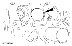
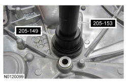
NOTE:
Use Spindle Bearing Installer 205-149 to install the seal.
Using the Spindle Bearing Installer, install the front cover radial seal from the rear side of the front cover.
NOTICE:
Failure to use Motorcraft® High Performance Engine RTV Silicone may cause the engine oil to foam excessively and result in serious engine damage.
NOTE:
The engine front cover and bolts 1, 2, 7, 8, 16, 17, 18, 19, 20 and 21 must be installed within 4 minutes of the initial sealant application. The remainder of the engine front cover bolts and the engine mount bracket bolts must be installed and tightened within 35 minutes of the initial sealant application. If the time limits are exceeded, the sealant must be removed, the sealing area cleaned and sealant reapplied. To clean the sealing area, use silicone gasket remover and metal surface prep. Failure to follow this procedure can cause future oil leakage.
Apply a 3.0 mm (0.11 in) bead of Motorcraft® High Performance Engine RTV Silicone to the engine front cover sealing surfaces including the 2 engine front cover bolt bosses.
- Apply a 5.5 mm (0.21 in) bead of Motorcraft® High Performance Engine RTV Silicone to the oil pan-to-cylinder block joint and the cylinder head-to-cylinder block joint areas of the engine front cover in 5 places as indicated.
NOTE:
Make sure the 2 locating dowel pins are seated correctly in the cylinder block.
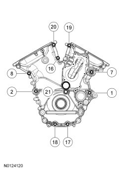
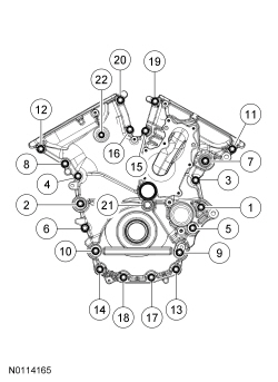
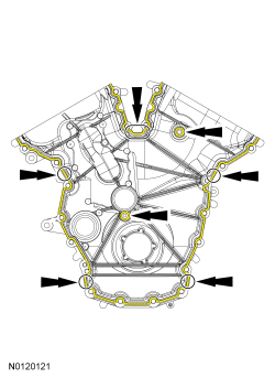
Install the engine front cover and bolts 1, 2, 7, 8, 16, 17, 18, 19, 20 and 21.
- Tighten in sequence to 3 Nm (27 lb-in).
- Install the remaining 18 engine front cover bolts. Tighten all of the engine front cover bolts in the sequence shown in 4 stages:
- Stage 1: Tighten bolts 1 through 21 to 10 Nm (89 lb-in).
- Stage 2: Tighten bolts 1 through 20 to 24 Nm (18 lb-ft).
- Stage 3: Tighten bolt 21 to 20 Nm (177 lb-in) then an additional 90 degrees.
- Stage 4: Tighten bolt 22 to 10 Nm (89 lb-in) then an additional 45 degrees.
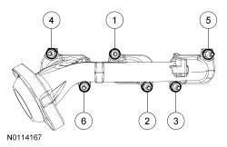
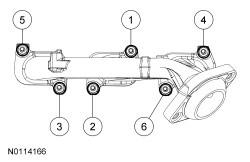
- Using a new gasket, install the oil filter adapter and the 5 bolts and tighten in sequence shown.
- Tighten to 10 Nm (89 lb-in) and then an additional 45 degrees.
- Install the Crankshaft Position (CKP) sensor and install the bolt.
- Tighten to 10 Nm (89 lb-in).
- Install the 2 RH Camshaft Position (CMP) sensors and the bolts.
- Tighten to 10 Nm (89 lb-in).
- Install the 2 LH
sensors and the bolts.
- Tighten to 10 Nm (89 lb-in).
- Install 6 new RH exhaust manifold studs.
- Tighten to 12 Nm (106 lb-in).
NOTICE:
Failure to tighten the exhaust manifold nuts to specification a second time will cause the exhaust manifold to develop an exhaust leak.
Using a new gasket, install the RH exhaust manifold and 6 new nuts. Tighten in 2 stages in the sequence shown:
- Stage 1: Tighten to 19 Nm (168 lb-in).
- Stage 2: Tighten to 25 Nm (18 lb-ft).
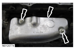
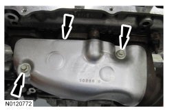
- Install the RH exhaust manifold heat shield and the 2 bolts.
- Tighten to 10 Nm (89 lb-in).
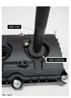
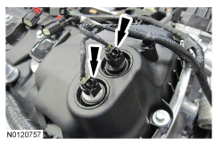
NOTE:
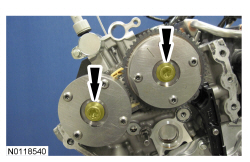
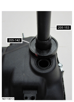
Installation of new seals is only required if damaged seals were removed.
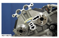
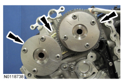
Using the
Spark Plug Tube Seal Installer and Handle, install new spark plug tube seals.
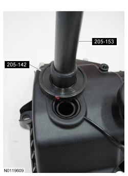
NOTE:
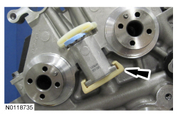
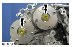
Installation of new seals is only required if damaged seals were removed.
Using the Differential Bearing Cone Installer and Handle, install new
solenoid seal(s).
NOTICE:
Failure to use the correct Motorcraft® High Performance Engine RTV Silicone may cause the engine oil to foam excessively and result in serious engine damage.
NOTE:
If the valve cover is not installed and the fasteners tightened within 4 minutes, the sealant must be removed and the sealing area cleaned. To clean the sealing area, use silicone gasket remover and metal surface prep. Failure to follow this procedure can cause future oil leakage.
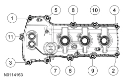
Apply an 8 mm (0.31 in) bead of Motorcraft® High Performance Engine RTV Silicone to the engine front cover-to-RH cylinder head joints.
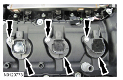
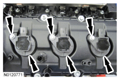
- Using a new gasket, install the RH valve cover and tighten the 3 bolts and 8 stud bolts in the sequence shown.
- Tighten to 10 Nm (89 lb-in).
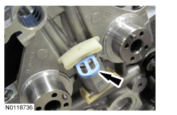
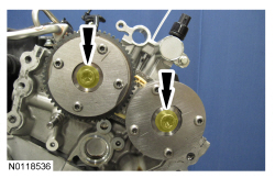
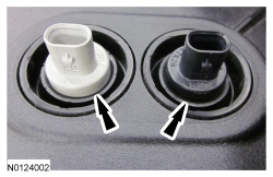
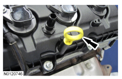
- Ensure the
seals in the valve cover are below the top of the
oil control solenoid electrical connector or the
seal may leak oil.
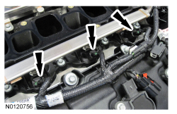
NOTICE:
Only use hand tools when installing the spark plugs, or damage may occur to the cylinder head or spark plug.
Install the 3 RH spark plugs.
- Tighten to 15 Nm (133 lb-in).
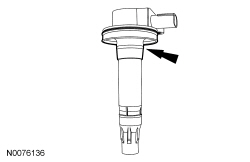
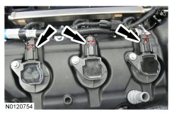
- Inspect the coil seals for rips, nicks or tears. Remove and discard any damaged coil seals.
- To install, slide the new coil seal onto the coil until it is fully seated at the top of the coil.
- Install the 3 RH ignition coil-on-plug assemblies and the 3 bolts.
- Tighten to 7 Nm (62 lb-in).
- Install 6 new LH exhaust manifold studs.
- Tighten to 12 Nm (106 lb-in).
NOTICE:
Failure to tighten the exhaust manifold nuts to specification a second time will cause the exhaust manifold to develop an exhaust leak.
Using a new gasket, install the LH exhaust manifold and 6 new nuts. Tighten in 2 stages in the sequence shown:
- Stage 1: Tighten to 19 Nm (168 lb-in).
- Stage 2: Tighten to 25 Nm (18 lb-ft).
- Install the LH exhaust manifold heat shield and the 2 bolts.
- Tighten to 10 Nm (89 lb-in).
NOTE:
Installation of new seals is only required if damaged seals were removed.
Using the
Spark Plug Tube Seal Installer and Handle, install new spark plug tube seals.
NOTE:
Installation of new seals is only required if damaged seals were removed.
Using the Differential Bearing Cone Installer and Handle, install new
solenoid seal(s).
NOTICE:
Failure to use the correct Motorcraft® High Performance Engine RTV Silicone may cause the engine oil to foam excessively and result in serious engine damage.
NOTE:
If the valve cover is not installed and the fasteners tightened within 4 minutes, the sealant must be removed and the sealing area cleaned. To clean the sealing area, use silicone gasket remover and metal surface prep. Failure to follow this procedure can cause future oil leakage.
Apply an 8 mm (0.31 in) bead of Motorcraft® High Performance Engine RTV Silicone to the engine front cover-to-LH cylinder head joints.
- Using a new gasket, install the LH valve cover and tighten the 4 bolts and 7 stud bolts in the sequence shown.
- Tighten to 10 Nm (89 lb-in).
- Ensure the
seals in the valve cover are below the top of the
oil control solenoid electrical connector or the
seal may leak oil.
NOTICE:
Only use hand tools when installing the spark plugs, or damage may occur to the cylinder head or spark plug.
Install the 3 LH spark plugs.
- Tighten to 15 Nm (133 lb-in).
- Inspect the coil seals for rips, nicks or tears. Remove and discard any damaged coil seals.
- To install, slide the new coil seal onto the coil until it is fully seated at the top of the coil.
- Install the 3 LH ignition coil-on-plug assemblies and the 3 bolts.
- Tighten to 7 Nm (62 lb-in).
NOTE:
Lubricate the O-ring seal with clean engine coolant.
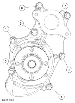
Using new coolant pump gasket and coolant pump O-ring seal, install the coolant pump and the 7 bolts and tighten in the sequence shown in 2 stages.
- Stage 1: Tighten to 10 Nm (89 lb-in).
- Stage 2: Tighten an additional 45 degrees.
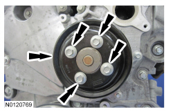
- Install the coolant pump pulley and the 4 bolts.
- Tighten to 24 Nm (18 lb-ft).
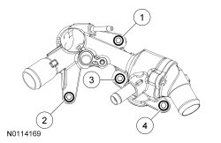
NOTE:
Lubricate the coolant inlet tube O-ring seal with clean engine coolant.
Install the thermostat housing and the 4 bolts and tighten in the sequence shown in 2 stages.
- Stage 1: Tighten to 8 Nm (71 lb-in).
- Stage 2: Tighten an additional 45 degrees.
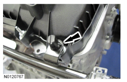
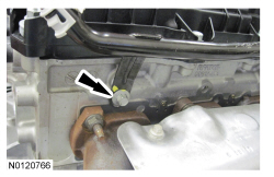
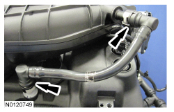
- Attach the heater tube retainer to the RH valve cover stud bolt.
- Install the heater tube bolt.
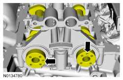
- Tighten to 23 Nm (17 lb-ft).
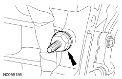
- Install the RH cylinder block drain plug.
- Tighten to 16 Nm (142 lb-in) plus an additional 180 degrees.
- Install the LH cylinder block drain plug or, if equipped, the block heater.
- Tighten the cylinder block drain plug to 10 Nm (89 lb-in) plus an additional 720 degrees.
- Tighten the block heater to 40 Nm (30 lb-ft).
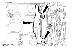
- Install the accessory drive belt tensioner and the 2 bolts.
- Tighten to 25 Nm (18 lb-ft).
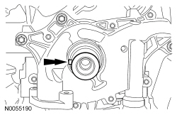
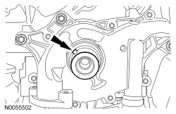
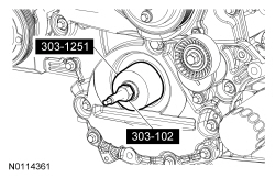
NOTE:
Apply clean engine oil to the crankshaft front seal bore in the engine front cover.
Using the Front Crankshaft Seal Installer and Crankshaft Vibration Damper Installer, install a new crankshaft front seal.
- Lubricate the crankshaft front seal inner lip with clean engine oil.
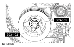
NOTE:
Lubricate the outside diameter sealing surfaces with clean engine oil.
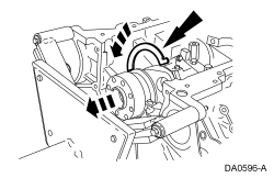
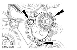
Using the Front Cover Oil Seal Installer and Crankshaft Vibration Damper Replacer, install the crankshaft pulley.
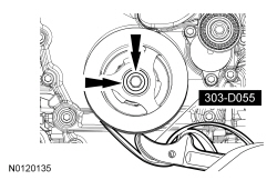
- Using the Strap Wrench, install the crankshaft pulley washer and new bolt and tighten in 4 stages.
- Stage 1: Tighten to 120 Nm (89 lb-ft).
- Stage 2: Loosen one full turn.
- Stage 3: Tighten to 50 Nm (37 lb-ft).
- Stage 4: Tighten an additional 90 degrees.
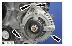
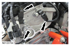
- Install the generator stud and position the generator and install the nut and bolt.
- Tighten the stud to 8 Nm (71 lb-in).
- Tighten the nut and bolt to 48 Nm (35 lb-ft).
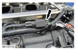
- Attach all of the wiring harness retainers to the LH valve cover and stud bolts.
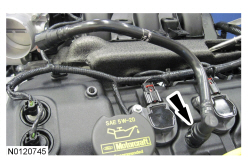
- Connect the
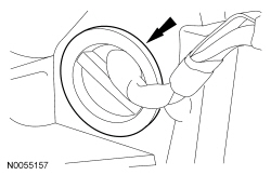
sensor electrical connector.
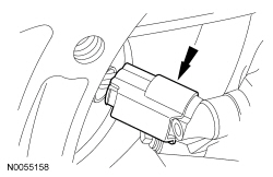
- Install the wiring harness grommet.
- Install the wiring harness retainer stud bolt.
- Tighten to 10 Nm (89 lb-in).
- Install the heat shield, the nut and the bolt.
- Tighten to 10 Nm (89 lb-in).
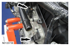
- Connect the 2 LH
sensors electrical connectors.
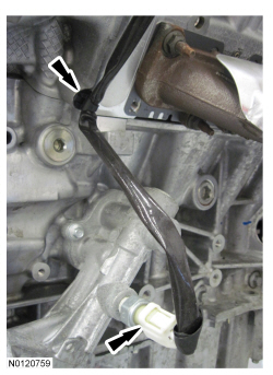
- Attach the wiring harness retainer to the rear of the cylinder head.
- Connect the
sensor electrical connector.
- Connect the 2 LH
solenoid electrical connectors.
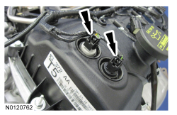
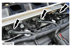
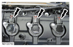
- Connect the 3 LH fuel rail electrical connectors.
- Connect the 3 LH ignition coil-on-plug electrical connectors.
- Connect the Engine Oil Pressure (EOP) switch electrical connector.
- Attach the
switch wiring harness retainer to the cylinder head.
- Attach all of the wiring harness retainers to the RH valve cover and stud bolts.
- Connect the 2 RH
sensors electrical connectors.
- Connect the 2 RH
solenoid electrical connectors.
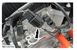
- Connect the 3 RH fuel rail electrical connectors.
- Connect the
sensor wiring harness jumper electrical connector.
- Connect the 3 RH ignition coil-on-plug electrical connectors.
- Install the RH fuel rail insulator.
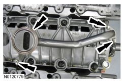
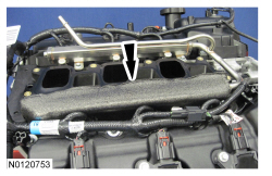
NOTICE:
If the engine is repaired or replaced because of upper engine failure, typically including valve or piston damage, check the intake manifold for metal debris. If metal debris is found, install a new intake manifold. Failure to follow these instructions can result in engine damage.
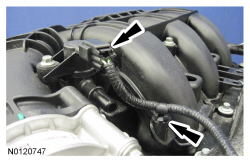
Using new gaskets, install the upper intake manifold and tighten the 7 bolts in the sequence shown in 2 stages.
- Stage 1: Tighten to 10 Nm (89 lb-in).
- Stage 2: Tighten an additional 45 degrees.
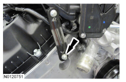
- Install the upper intake manifold support bracket bolt to the RH cylinder head.
- Tighten to 10 Nm (89 lb-in).
- Install the LH fuel rail insulator.
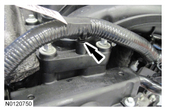
- Attach the wiring harness pin-type retainer to the rear of the upper intake manifold.
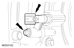
- Connect the PCV tube quick connect couplings to the PCV valve and intake manifold. For additional information, refer to
Section 310-00
.
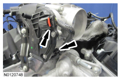
- Connect the Throttle Body (TB) electrical connector.
- Attach the
electrical connector wiring harness pin-type retainer to the
.
- Connect the Evaporative Emission (EVAP) canister purge valve electrical connector.
- Attach the
canister purge valve electrical connector wiring harness pin-type retainer.
- Install the engine oil level indicator.
- Install the crankcase vent tube. For additional information, refer to
Section 310-00
.
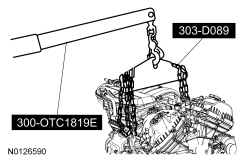
- Install the LH engine lift eye.
- Install the RH front lift eye.
- Using the Floor Crane and Spreader Bar, remove the engine from the stand.
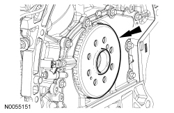
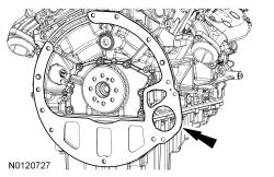
- Install the crankshaft sensor ring.
NOTE:
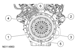
Flexplate shown, flywheel similar.
Install the spacer plate.
Engines with manual transmission
NOTE:
The dual mass flywheel normally has up to a total of 14 degrees (6.5 ring gear teeth) maximum rotational freeplay between the primary (bolted to crankshaft) and the secondary mass (clutch disc face).
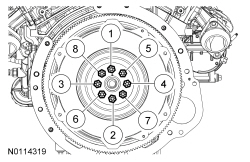
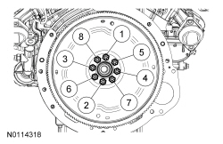
Install the flywheel and the 8 bolts and tighten is sequence shown.
- Tighten to 80 Nm (59 lb-ft).
NOTE:
If installing the original pressure plate, align it using the index marks made during removal.
NOTE:
Always install new pressure plate bolts.
Using a suitable clutch aligner, position the clutch disc on the flywheel, install the pressure plate and 6 new pressure plate bolts. Turn the bolts 1-2 turns at a time in a star pattern until the clutch is fully secured.
- Tighten the pressure plate bolts in 2 stages in a star pattern
- Stage 1: Tighten to 47 Nm (35 lb-ft).
- Stage 2: Tighten an additional 60 degrees.
Engines with automatic transmission
- Install the flexplate and the 8 bolts and tighten is sequence shown.
- Tighten to 80 Nm (59 lb-ft).