300-OTC1819E

303-D089 (D93P-6001-A3) or equivalent

SECTION 303-01A: Engine — 3.7L
| 2014 Mustang Workshop Manual
|
INSTALLATION
| Procedure revision date: 01/07/2013
|
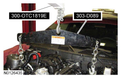
| 2,200# Floor Crane, Fold Away
300-OTC1819E |
| Spreader Bar
303-D089 (D93P-6001-A3) or equivalent |
| Vehicle Communication Module (VCM) and Integrated Diagnostic System (IDS) software with appropriate hardware, or equivalent scan tool
|
| Item | Specification |
|---|---|
| Motorcraft® SAE 5W-20 Premium Synthetic Blend Motor Oil (US); Motorcraft® SAE 5W-20 Super Premium Motor Oil (Canada)
XO-5W20-QSP (US); CXO-5W20-LSP12 (Canada) | WSS-M2C945-A |
| Motorcraft® Multi-Purpose Grease
XL-5 | ESB-M1C93-B |
 WARNING: Do not smoke, carry lighted tobacco or have an open flame of any type when working on or near any fuel-related component. Highly flammable mixtures are always present and may be ignited. Failure to follow these instructions may result in serious personal injury.
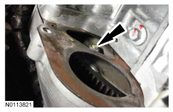
NOTICE: Prior to installation of the engine, the torque converter pilot hub must be lubricated with multi-purpose grease or damage to the torque converter or the engine crankshaft can occur.
Lubricate the torque converter pilot hub with multi-purpose grease.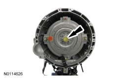
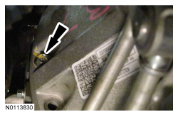
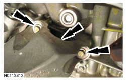
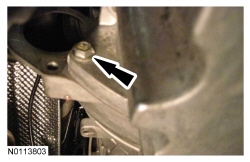
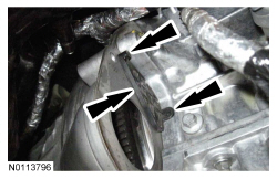
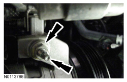
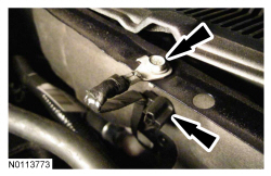
NOTE: LH shown, RH similar.
Install the new 2 LH and RH catalytic convertor-to-exhaust manifold nuts.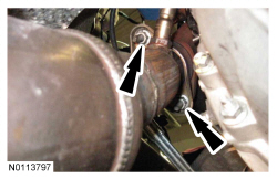
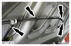
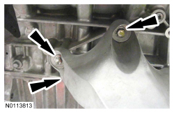
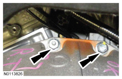
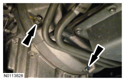
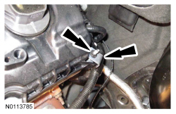
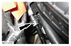
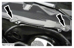
NOTE: RH shown, LH similar.
Install the front crossmember brace and the 4 nuts (2 shown).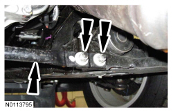
NOTE: Do not lubricate the engine oil filter gasket.
Install a new engine oil filter.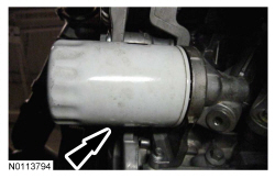
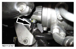
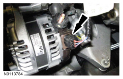
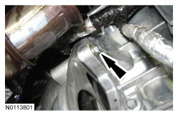
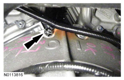
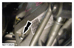
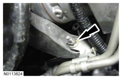
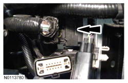
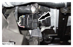
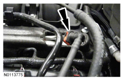
NOTE: RH shown, LH similar.
Connect and attach the RH and LH Heated Oxygen Sensor (HO2S) electrical connectors.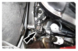
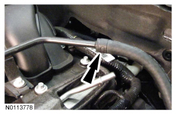
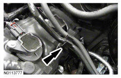
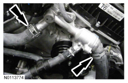
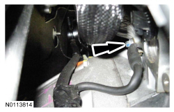
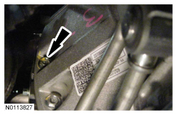
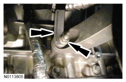
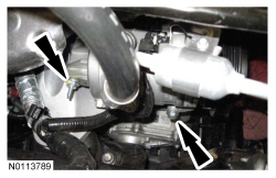
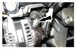
NOTE: RH shown, LH similar.
Install the RH and LH engine mount bracket-to-engine mount nuts.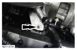
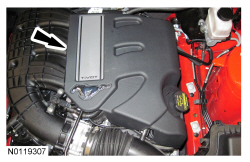
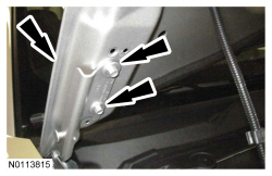
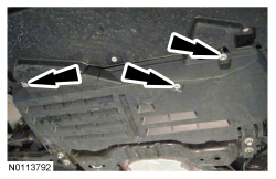
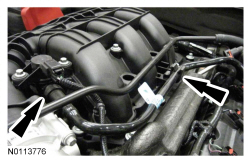
NOTE: LH shown, RH similar.
If equipped, install the strut tower cross brace and the 4 nuts (2 shown).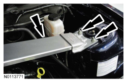
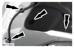
NOTE: RH shown, LH similar.
Align the hood and install the 4 bolts (2 shown).