
303-050 (T70P-6000)

303-F070

303-F072
SECTION 303-01B: Engine — 5.0L (4V)
| 2014 Mustang Workshop Manual
|
IN-VEHICLE REPAIR
| Procedure revision date: 01/07/2013
|
| Lifting Bracket, Engine
303-050 (T70P-6000) |
| Support Bar, Engine
303-F070 |
| Support Bar, Engine
303-F072 |
| Item | Part Number | Description |
|---|---|---|
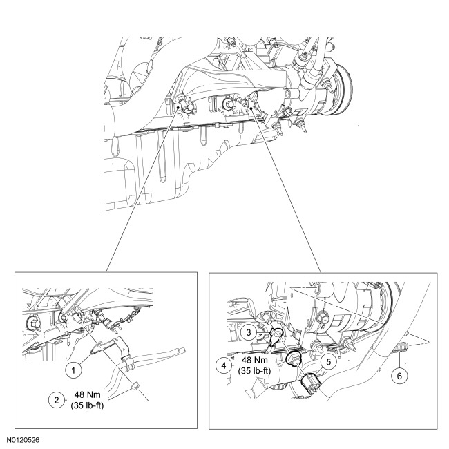
| 1 | — | Transmission cooler tube bracket (part of 7R081B) |
| 2 | W520103 | Transmission cooler tube bracket nut |
| 3 | 14290 | Ground cable |
| 4 | W520103 | Ground cable nut |
| 5 | — | Wiring harness retainer (part of 12A581) |
| 6 | — | Wiring harness retainer (part of 12A581) |
| Item | Part Number | Description |
|---|---|---|
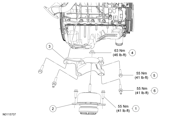
| 1 | W707641 | RH engine support insulator-to-subframe bolt (2 required) |
| 2 | 6038 | RH engine support insulator |
| 3 | 6037 | RH engine support insulator bracket |
| 4 | W712530 | RH engine support insulator nut |
| 5 | W500723 | RH engine support insulator bracket bolt (2 required) |
| 6 | W714924 | RH engine support insulator bracket stud bolt (2 required) |
| Item | Part Number | Description |
|---|---|---|
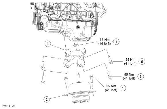
| 1 | W707641 | LH engine support insulator-to-subframe bolt (2 required) |
| 2 | 6038 | LH engine support insulator |
| 3 | 6B033 | LH engine support insulator bracket |
| 4 | W712530 | LH engine support insulator nut |
| 5 | W500723 | LH engine support insulator bracket bolt (3 required) |
| 6 | W714924 | LH engine support insulator bracket stud bolt |
Removal and Installation
All LH and/or RH engine support insulators
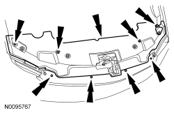
NOTE: The engine appearance cover rubber grommets may remain on the cover. If so, remove the grommets from the cover and install them on the intake manifold before installing the cover.
If equipped, remove the engine appearance cover.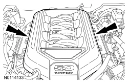
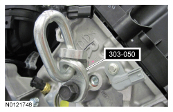
NOTE: It may be necessary to install washers between the Engine Lifting Bracket and the cylinder head to prevent the Engine Lifting Bracket from contacting the valve cover while supporting the engine.
Install an Engine Lifting Bracket on the side of the LH cylinder head.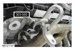
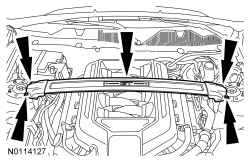
NOTE: The draw screw and bracket from the heavy duty Engine Support Bar (303-F070) must be used with the light duty Engine Support Bar (303-F072). This will provide enough clearance between the draw screw bracket and the cowl.
Install the Engine Support Bar.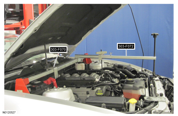
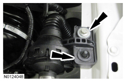
NOTE: RH shown, LH similar.
Remove the RH and LH engine support insulator nuts.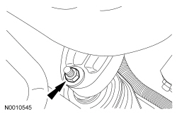
All LH engine support insulators
All RH engine support insulators
All LH and/or RH engine support insulators