
303-050 (T70P-6000)

303-F070

303-F072
SECTION 303-01B: Engine — 5.0L (4V)
| 2014 Mustang Workshop Manual
|
IN-VEHICLE REPAIR
| Procedure revision date: 01/07/2013
|
| Lifting Bracket, Engine
303-050 (T70P-6000) |
| Support Bar, Engine
303-F070 |
| Support Bar, Engine
303-F072 |
| Item | Specification |
|---|---|
| Motorcraft® Metal Surface Prep
ZC-31-A | — |
| Item | Part Number | Description |
|---|---|---|
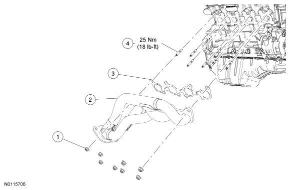
| 1 | W714870 | RH exhaust manifold nuts (8 required) |
| 2 | 9430 | RH exhaust manifold |
| 3 | 9448 | RH exhaust manifold gasket |
| 4 | W714869 | RH exhaust manifold studs (8 required) |
Removal
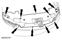
NOTE: The engine appearance cover rubber grommets may remain on the cover. If so, remove the grommets from the cover and install them on the intake manifold before installing the cover.
If equipped, remove the engine appearance cover.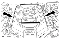
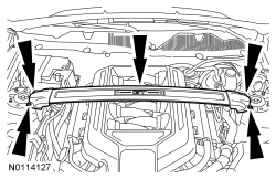
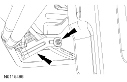
NOTE: The draw screw and bracket from the heavy duty Engine Support Bar (303-F070) must be used with the light duty Engine Support Bar (303-F072). This will provide enough clearance between the draw screw bracket and the cowl.
Install the Engine Support Bar.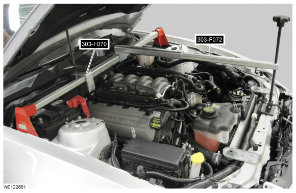
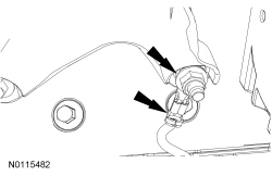
NOTE: RH shown, LH similar.
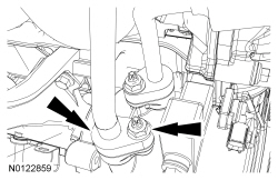
Remove the RH and LH engine support insulator nuts.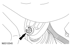
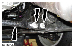
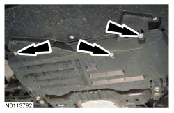
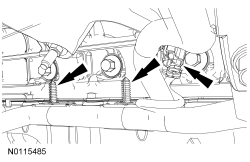
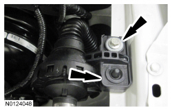
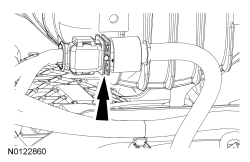
NOTE: The RH engine support insulator has been removed from the graphic for clarity.
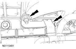
Remove the 2 bolts, the 2 stud bolts and the RH engine support insulator bracket.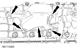
Installation
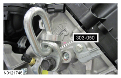
NOTICE: Do not use metal scrapers, wire brushes, power abrasive discs or other abrasive means to clean the sealing surfaces. These tools cause scratches and gouges which make leak paths. Use a plastic scraper to clean the sealing surfaces.
Clean the exhaust manifold mating surface of the cylinder head with metal surface prep. Follow the directions on the packaging.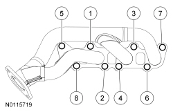
NOTE: The engine support insulator bracket must be positioned on the engine support insulator stud. If necessary, adjust the height of the engine using the engine support bar.
Install the RH engine support insulator bracket, the 2 bolts and the 2 stud bolts.NOTE: RH shown, LH similar.
Install the RH and LH engine support insulator nuts.NOTE: The engine appearance cover rubber grommets may remain on the cover. If so, remove the grommets from the cover and install them on the intake manifold before installing the cover.
If equipped, install the engine appearance cover.