SECTION 303-01B: Engine — 5.0L (4V)
| 2014 Mustang Workshop Manual
|
IN-VEHICLE REPAIR
| Procedure revision date: 01/07/2013
|
Intake Manifold
Material
| Item
| Specification
|
|---|
Motorcraft® Metal Surface Prep
ZC-31-A
| —
|
Hoses and Supports
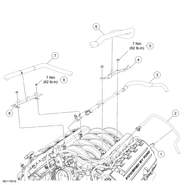
| Item
| Part Number
| Description
| | 1
| —
| Fuel supply tube retaining clip (part of 9J280)
|
| 2
| 9J280
| Fuel supply tube
|
| 3
| 9C482
| Vacuum tube
|
| 4
| 18D690
| LH heater hose support
|
| 5
| W713946
| LH heater hose support nut (2 required)
|
| 6
| 18472
| LH heater hose
|
| 7
| 18472
| RH heater hose
|
| 8
| 18D690
| RH heater hose support
|
| 9
| W713946
| RH heater hose support nut (2 required)
|
Wiring Harness and Emission tubes
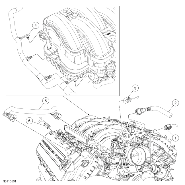
| Item
| Part Number
| Description
| | 1
| —
| Throttle body electrical connector (part of 12A581)
|
| 2
| 9G271
| Fuel vapor tube
|
| 3
| —
| Evaporative Emission (EVAP) canister purge valve electrical connector (part of 12A581)
|
| 4
| —
| Wiring harness retainer (part of 12A581) (4 required)
|
| 5
| 6K817
| Crankcase vent tube
|
| 6
| —
| Fuel injector electrical connector (part of 12A581) (8 required)
|
Fuel Rail Insulators, Intake Manifold and Gaskets
NOTE:
Refer to the on-line Workshop Manual to view this illustration as an interactive exploded view, requires Adobe® Acrobat® 8.0 or higher.
NOTE:
Refer to the on-line Workshop Manual to learn about using an Interactive Illustration.
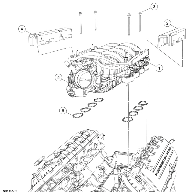
| Item
| Part Number
| Description
| | 1
| 9Y450
| Intake manifold bolt (part of 9424) (6 required)
|
| 2
| 6P013
| LH fuel rail insulator
|
| 3
| W714864
| Fuel rail bolt (4 required)
|
| 4
| 6P013
| RH fuel rail insulator
|
| 5
| 9424
| Intake manifold
|
| 6
| 9439
| Intake manifold gasket
|
Removal
 WARNING: Do not smoke, carry lighted tobacco or have an open flame of any type when working on or near any fuel-related component. Highly flammable mixtures are always present and may be ignited. Failure to follow these instructions may result in serious personal injury.
WARNING: Before working on or disconnecting any of the fuel tubes or fuel system components, relieve the fuel system pressure to prevent accidental spraying of fuel. Fuel in the fuel system remains under high pressure, even when the engine is not running. Failure to follow this instruction may result in serious personal injury.
- Release the fuel system pressure. For additional information, refer to
Section 310-00
.
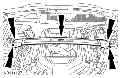
- If equipped, remove the 4 nuts and the strut tower cross brace.
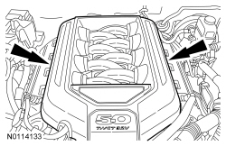
NOTE:
The engine appearance cover rubber grommets may remain on the cover. If so, remove the grommets from the cover and install them on the intake manifold before installing the cover.
Remove the engine appearance cover.
- Remove the Air Cleaner (ACL) outlet pipe. For additional information, refer to
Section 303-12
.
- Disconnect the Throttle Body (TB) electrical connector.
- Disconnect the Evaporative Emission (EVAP) canister purge valve tube and electrical connector. For additional information, refer to the quick connect coupling procedure in
Section 310-00
.
- Remove the crankcase ventilation tube. For additional information, refer to the quick connect coupling procedure in
Section 310-00
.
- Disconnect the fuel supply tube. For additional information refer to the quick connect procedure in
Section 310-00
.
- Disconnect the vacuum tube from the intake manifold.
- Position the heater hoses aside.
- Remove the 2 nuts and the LH heater hose support.
- Position the vacuum tube assembly aside.
- Remove the 2 nuts and the RH heater hose support.
- Remove the LH and RH fuel rail insulators.
- Disconnect the 8 fuel injector electrical connectors.
- Detach the 4 wiring harness retainers from the rear of the intake manifold.
NOTE:
It is not necessary to remove the fuel rail from the intake manifold assembly.
Remove the 4 fuel rail bolts.
- Loosen the 6 bolts and remove the intake manifold.
Installation
NOTICE:
If the engine is repaired or replaced because of upper engine failure, typically including valve or piston damage, check the intake manifold for metal debris. If metal debris if found, install a new intake manifold. Failure to follow these instructions can result in engine damage.
NOTE:
Clean the sealing surfaces with metal surface prep. Follow the directions on the packaging. Inspect the mating surfaces.
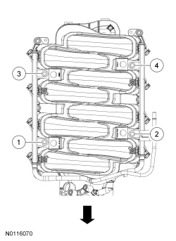
NOTE:
Fuel rail removed from graphic for clarity.
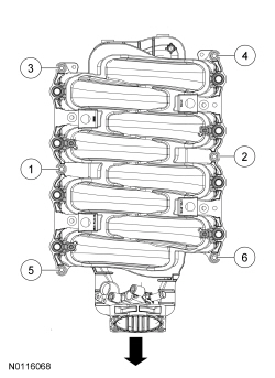
Using new gaskets, install the intake manifold.
- Tighten the 6 intake manifold bolts in the sequence shown in 2 stages.
- Stage 1: Tighten to 10 Nm (89 lb-in).
- Stage 2: Tighten an additional 45 degrees.
- Install the 4 fuel rail bolts.
- Tighten in the sequence shown in 3 stages.
- Stage 2: Tighten to 10 Nm (89 lb-in).
- Stage 2: Tighten an additional 90 degrees.
- Attach the 4 wiring harness retainers to the rear of the intake manifold.
- Connect the 8 fuel injector electrical connectors.
- Install the LH and RH fuel rail insulators.
- Install the RH heater hose support and the 2 nuts.
- Tighten to 7 Nm (62 lb-in).
- Install the vacuum tube assembly, the LH heater hose support and the 2 nuts.
- Tighten to 7 Nm (62 lb-in).
- Position the heater hoses.
- Connect the vacuum tube to the intake manifold.
- Connect the fuel supply tube. For additional information, refer to
Section 310-00
.
- Install the crankcase ventilation tube. For additional information, refer to
Section 310-00
.
- Connect the Evaporative Emission (EVAP) purge valve tube and electrical connector. For additional information, refer to
Section 310-00
.
- Connect the
electrical connector.
- Install the Air Cleaner (ACL) outlet pipe. For additional information, refer to
Section 303-12
.
NOTE:
The engine appearance cover rubber grommets may remain on the cover. If so, remove the grommets from the cover and install them on the intake manifold before installing the cover.
Install the engine appearance cover.
- If equipped, install the strut tower cross brace and the 4 nuts.
- Tighten to 35 Nm (26 lb-ft).