
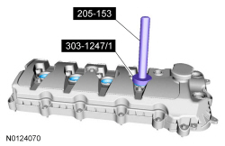
205-153 (T80T-4000-W)

205-142 (T80T-4000-J)

303-1247/2

303-1247/1
SECTION 303-01B: Engine — 5.0L (4V)
| 2014 Mustang Workshop Manual
|
IN-VEHICLE REPAIR
| Procedure revision date: 01/07/2013
|
| Handle
205-153 (T80T-4000-W) |
| Installer, Differential Bearing Cone
205-142 (T80T-4000-J) |
| Installer, Spark Plug Tube Seal
303-1247/2 |
| Remover, Spark Plug Tube Seal
303-1247/1 |
| Item | Specification |
|---|---|
| Motorcraft® Metal Surface Prep
ZC-31-A | — |
| Motorcraft® Silicone Gasket Remover
ZC-30 | — |
| Motorcraft® Silicone Gasket and Sealant
TA-30 | WSE-M4G323-A4 |
| Item | Part Number | Description |
|---|---|---|
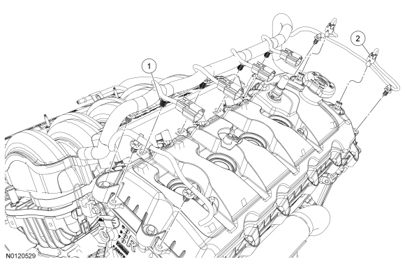
| 1 | — | Wiring harness retainer (part of 12A581) (9 required) |
| 2 | — | Variable Camshaft Timing (VCT) variable force solenoid electrical connector (part of 12A581) (2 required) |
| Item | Part Number | Description |
|---|---|---|
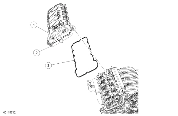
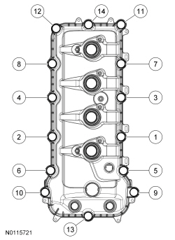
| 1 | — | Valve cover bolt (part of 6582) (14 required) |
| 2 | 6582 | RH valve cover |
| 3 | 6584 | RH valve cover gasket |
| Item | Part Number | Description |
|---|---|---|
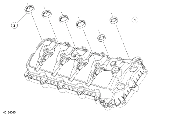
| 1 | 6C535 | Variable Camshaft Timing (VCT) variable force solenoid seal (2 required) |
| 2 | 6C535 | Spark plug tube seal (4 required) |
Removal
NOTICE: During engine repair procedures, cleanliness is extremely important. Any foreign material, including any material created while cleaning gasket surfaces, that enters the oil passages, coolant passages or the oil pan, can cause engine failure.
NOTE: The engine appearance cover rubber grommets may remain on the cover. If so, remove the grommets from the cover and install them on the intake manifold before installing the cover.
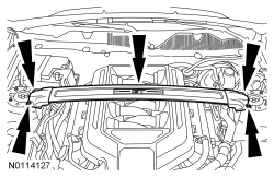
Remove the engine appearance cover.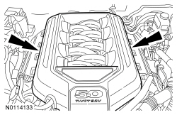
NOTICE: Do not use metal scrapers, wire brushes, power abrasive discs or other abrasive means to clean the sealing surfaces. These tools cause scratches and gouges which make leak paths. Use a plastic scraping tool to remove all traces of old sealant.
Loosen the 14 bolts and remove the RH valve cover and gasket.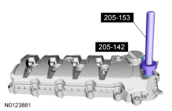
Installation
NOTE: Installation of new seals is only required if damaged seals were removed.
Using the VCT Spark Plug Tube Seal Installer and Handle, install new spark plug tube seals.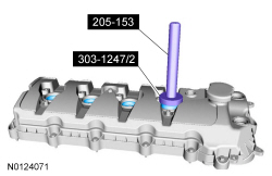
NOTE: Installation of new seals is only required if damaged seals were removed.
Using the Differential Bearing Cone Installer and Handle, install new VCT variable force solenoid seal(s).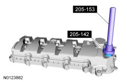
NOTE: If the valve cover is not installed and the fasteners tightened within 5 minutes, the sealant must be removed and the sealing area cleaned. To clean the sealing area, use silicone gasket remover and metal surface prep. Failure to follow this procedure can cause future oil leakage.
Apply an 8 mm (0.31 in) bead of silicone gasket and sealant to the engine front cover-to-RH cylinder head joints.
NOTE: The engine appearance cover rubber grommets may remain on the cover. If so, remove the grommets from the cover and install them on the intake manifold before installing the cover.
Install the engine appearance cover.