Special Tool(s)
 | 2,200# Floor Crane, Fold Away
300-OTC1819E
|
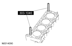
 | Alignment Pins, Cylinder Head
303-1040 (SR-015486)
|
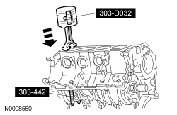
 | Compressor, Piston Ring
303-D032 (D81L-6002-C) or equivalent
|
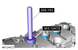
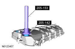
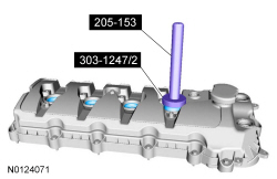
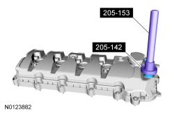
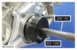
 | Handle
205-153 (T80T-4000-W)
|
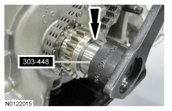
 | Holding Tool, Crankshaft
303-448 (T93P-6303-A)
|
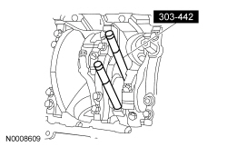
 | Installer, Connecting Rod
303-442 (T93P-6136-A)
|
 | Installer, Differential Bearing Cone
205-142 (T80T-4000-J)
|
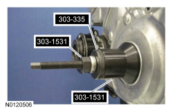
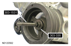
 | Installer, Front Cover Oil Seal
303-335 (T88T-6701-A2 plate only)
|
 | Installer, Front Crank Seal and Damper
303-1531
|
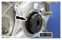
 | Installer, Rear Main Seal
303-1250
|
 | Installer, Spark Plug Tube Seal
303-1247/2
|
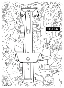
 | Lifting Bracket, Engine
303-F047 (014-00073) or equivalent
|
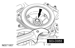
 | Strap Wrench
303-D055 (D85L-6000-A) or equivalent
|
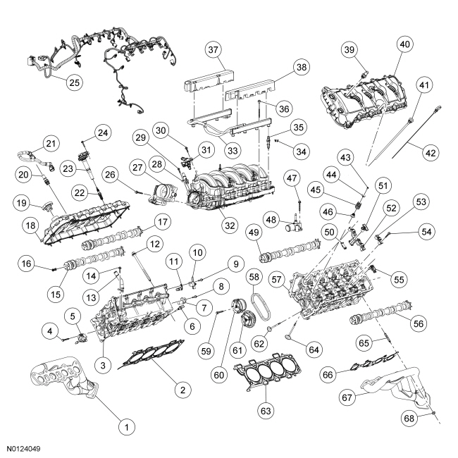
| Item
| Part Number
| Description
| | 1
| 9430
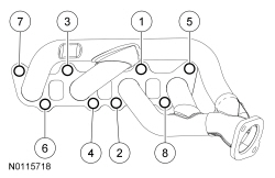
| RH Exhaust manifold
|
| 2
| 6051
| RH cylinder head gasket
|
| 3
| 6049
| RH cylinder head
|
| 4
| N807352
| Primary timing chain tensioner bolt (4 required)
|
| 5
| 6L266
| Primary timing chain tensioner (2 required)
|
| 6
| 6G004
| Cylinder Head Temperature (CHT) sensor
|
| 7
| 6B288
| Camshaft Position (CMP) sensor (2 required)
|
| 8
| W503277
| sensor bolt (2 required)
|
| 9
| W503277
| Radio capacitor bolt (2 required)
|
| 10
| 18801
| Radio capacitor (2 required)
|
| 11
| 12K073
| Camshaft transducer (2 required)
|
| 12
| 6065
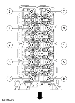
| Cylinder head bolt (20 required)
|
| 13
| 18696
| Heater supply tube
|
| 14
| W503277
| Heater supply tube bolt
|
| 15
| 6250
| RH exhaust camshaft
|
| 16
| 6C683
| Camshaft engine oil filter (4 required)
|
| 17
| 6250
| RH intake camshaft
|
| 18
| 6582
| RH valve cover
|
| 19
| 6766
| Oil filler cap
|
| 20
| 6A666
| PCV valve
|
| 21
| 6578
| Crankcase vent hose
|
| 22
| 12405
| Spark plug (8 required)
|
| 23
| 12029
| Ignition coil on plug (8 required)
|
| 24
| W714507
| Ignition coil on plug bolt (8 required)
|
| 25
| 12A581
| Engine wiring harness
|
| 26
| W714866
| Throttle Body (TB) bolt (4 required)
|
| 27
| 9F991
|
|
| 28
| 9F624
| Plenum heat control inlet tube
|
| 29
| W710652
| Plenum heat control inlet tube bolt
|
| 30
| W503278
| Fuel vapor purge valve bolt (2 required)
|
| 31
| 9C915
| Fuel vapor purge valve
|
| 32
| 9424
| Intake manifold
|
| 33
| 9F792
| Fuel rail
|
| 34
| 9C995
| Fuel injector clip (8 required)
|
| 35
| 9F593
| Fuel injector (8 required)
|
| 36
| W714864
| Fuel rail bolt (4 required)
|
| 37
| 6P013
| RH fuel injector insulator shield
|
| 38
| 6P013
| LH fuel injector insulator shield
|
| 39
| 6762
| Crankcase vent valve
|
| 40
| 6582
| LH valve cover
|
| 41
| 6754
| Oil indicator tube
|
| 42
| 6750
| Oil indicator
|
| 43
| 6518
| Valve spring retainer key (64 required)
|
| 44
| 6514
| Valve spring retainer (32 required)
|
| 45
| 6513
| Valve spring (32 required)
|
| 46
| 6571
| Valve stem seal (32 required)
|
| 47
| W714866
| Coolant outlet connector bolt (2 required)
|
| 48
| 8594
| Coolant outlet connector
|
| 49
| 6250
| LH intake camshaft
|
| 50
| 6K297
| Secondary tensioner shoe (2 required)
|
| 51
| 6K254
| Secondary tensioner (2 required)
|
| 52
| —
| Camshaft bearing cap (part of 6049) (2 required)
|
| 53
| —
| Camshaft bearing cap (part of 6049) (16 required)
|
| 54
| N806183
| Camshaft bearing cap bolt (40 required)
|
| 55
| 6500/6564
| Hydraulic lash adjuster/camshaft roller follower (32 required)
|
| 56
| 6250
| LH exhaust camshaft
|
| 57
| 6049
| LH cylinder head
|
| 58
| 6268
| Secondary timing chain (2 required)
|
| 59
| 6279
| Camshaft sprocket bolt (12 required)
|
| 60
| 6256
| Intake camshaft Variable Camshaft Timing (VCT) (2 required)
|
| 61
| 6256
| Exhaust camshaft
(2 required)
|
| 62
| 6505
| Exhaust valve (16 required)
|
| 63
| 6051
| LH cylinder head gasket
|
| 64
| 6507
| Intake valve (16 required)
|
| 65
| W714869
| Exhaust manifold stud (16 required)
|
| 66
| 9448
| Exhaust manifold gasket (2 required)
|
| 67
| 9431
| LH exhaust manifold
|
| 68
| W714870
| Exhaust manifold nut (16 required)
|
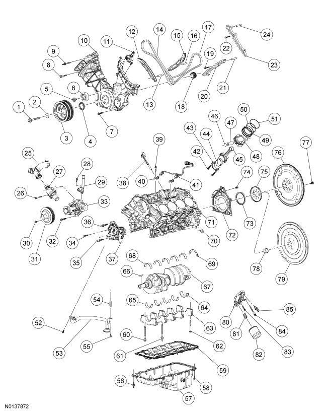
| Item
| Part Number
| Description
| | 1
| 6A340
| Crankshaft pulley bolt
|
| 2
| N807033
| Crankshaft pulley washer
|
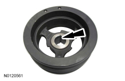
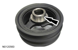
| 3
| 6316
| Crankshaft pulley
|
| 4
| 6700
| Crankshaft front oil seal
|
| 5
| W707288
| Accessory drive belt idler pulley bolt
|
| 6
| 19A216
| Accessory drive belt idler pulley
|
| 7
| W714925
| Engine front cover bolt (8 required)
|
| 8
| W704920
| Engine front cover bolt (5 required)
|
| 9
| W704919
| Engine front cover stud bolt (2 required)
|
| 10
| 6019
| Engine front cover
|
| 11
| 6B297
| Variable Camshaft Timing (VCT) variable force solenoid (4 required)
|
| 12
| 6K255
| RH timing chain tensioner arm
|
| 13
| W714258
| RH timing chain tensioner arm pin
|
| 14
| 6268
| RH primary timing chain
|
| 15
| 6K255
| LH timing chain tensioner arm
|
| 16
| W701501
| LH timing chain tensioner arm pin
|
| 17
| 6268
| LH primary timing chain
|
| 18
| 6306
| Crankshaft sprocket
|
| 19
| N807352
| LH timing chain guide bolt
|
| 20
| 6B274
| LH timing chain guide
|
| 21
| W714258
| LH timing chain guide pin
|
| 22
| N807352
| RH timing chain guide bolt
|
| 23
| 6M256
| RH timing chain guide
|
| 24
| W714258
| RH timing chain guide pin
|
| 25
| 8566
| Coolant bypass tee
|
| 26
| W713197
| Thermostat housing bolt (2 required)
|
| 27
| 8A586
| Thermostat housing
|
| 28
| W503277
| Heater outlet tube bolt
|
| 29
| 18663
| Heater outlet tube
|
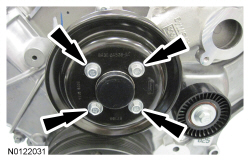
| 30
| N806282
| Coolant pump pulley bolt (4 required)
|
| 31
| 8509
| Coolant pump pulley
|
| 32
| W714925
| Coolant pump bolt
|
| 33
| 8501
| Coolant pump
|
| 34
| N806183
| Oil pump bolt (2 required)
|
| 35
| W714252
| Oil pump stud bolt
|
| 36
| W714251
| Oil pump stud bolt
|
| 37
| 6600
| Oil pump
|
| 38
| 6C315
| Crankshaft Position (CKP) sensor
|
| 39
| W500110
| Knock Sensor (KS) bolt (2 required)
|
| 40
| 12A699
| (2 required)
|
| 41
| 14A411
| wiring harness
|
| 42
| 6214
| Connecting rod cap bolt (16 required)
|
| 43
| —
| Connecting rod cap (part of 6200) (8 required)
|
| 44
| 6211
| Connecting rod bearing (16 required)
|
| 45
| 6200
| Connecting rod (8 required)
|
| 46
| 6140
| Piston pin retainer (16 required)
|
| 47
| 6135
| Piston pin (8 required)
|
| 48
| 6110
| Piston (8 required)
|
| 49
| —
| Outer oil control ring (part of 6148) (16 required)
|
| 50
| —
| Lower compression ring (part of 6148) (8 required)
|
| 51
| —
| Upper compression ring (part of 6148) (8 required)
|
| 52
| W714962
| Oil pump screen and pickup tube bolt (2 required)
|
| 53
| 6622
| Oil pump screen and pickup tube
|
| 54
| N806180
| Oil pump screen and pickup tube spacer
|
| 55
| N605904
| Oil pump screen and pickup tube bolt
|
| 56
| W714963
| Oil pan stud bolt (3 required)
|
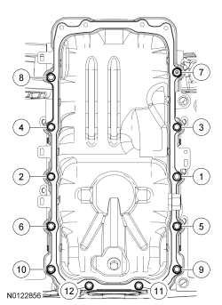
| 57
| 6675
| Oil pan
|
| 58
| W714962
| Oil pan bolt (13 required)
|
| 59
| 6C878
| Oil pan baffle and gasket
|
| 60
| 6345
| Crankshaft main bearing cap bolt (9 required)
|
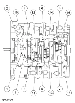
| 61
| 6K258
| Crankshaft main bearing cap stud bolt
|
| 62
| 6345
| Crankshaft main bearing cap bolt (10 required)
|
| 63
| —
| Crankshaft main bearing cap (part of 6010) (5 required)
|
| 64
| 6D309
| Crankshaft lower main bearing
|
| 65
| 6D309
| Crankshaft lower main bearing (4 required)
|
| 66
| N806201
| Woodruff key
|
| 67
| 6303
| Crankshaft
|
| 68
| 6D309
| Crankshaft upper main bearing (5 required)
|
| 69
| 6A341
| Thrust washer
|
| 70
| 6C358
| Crankshaft main bearing cap side bolt (10 required)
|
| 71
| 6010
| Engine block
|
| 72
| 6K318
| Crankshaft rear seal retainer plate
|
| 73
| 6701
| Crankshaft rear seal
|
| 74
| W714962
| Crankshaft rear seal retainer plate bolt (6 required)
|
| 75
| 12A227
| Crankshaft sensor ring
|
| 76
| 6375
| Flexplate
|
| 77
| 6379
| Flexplate bolt (8 required)
|
| 78
| 7120
| Input shaft bearing
|
| 79
| 6375
| Flywheel
|
| 80
| 6881
| Oil filter adapter
|
| 81
| 6890
| Oil filter mounting insert bolt
|
| 82
| 6731
| Oil filter
|
| 83
| W714974
| Oil filter adapter bolt (2 required)
|
| 84
| W503306
| Oil filter adapter bolt
|
| 85
| 9278
| Engine Oil Pressure (EOP) switch
|
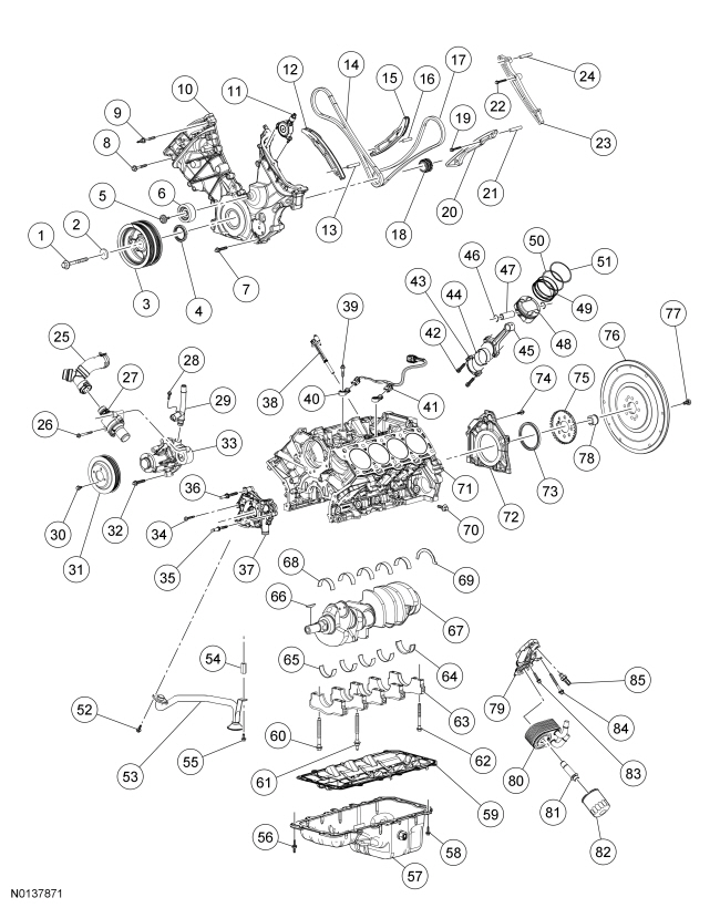
| Item
| Part Number
| Description
| | 1
| 6A340
| Crankshaft pulley bolt
|
| 2
| N807033
| Crankshaft pulley washer
|
| 3
| 6316
| Crankshaft pulley
|
| 4
| 6700
| Crankshaft front oil seal
|
| 5
| W707288
| Accessory drive belt idler pulley bolt
|
| 6
| 19A216
| Accessory drive belt idler pulley
|
| 7
| W714925
| Engine front cover bolt (8 required)
|
| 8
| W704920
| Engine front cover bolt (5 required)
|
| 9
| W704919
| Engine front cover stud bolt (2 required)
|
| 10
| 6019
| Engine front cover
|
| 11
| 6B297
| Variable Camshaft Timing (VCT) variable force solenoid (4 required)
|
| 12
| 6K255
| RH timing chain tensioner arm
|
| 13
| W714258
| RH timing chain tensioner arm pin
|
| 14
| 6268
| RH primary timing chain
|
| 15
| 6K255
| LH timing chain tensioner arm
|
| 16
| W701501
| LH timing chain tensioner arm pin
|
| 17
| 6268
| LH primary timing chain
|
| 18
| 6306
| Crankshaft sprocket
|
| 19
| N807352
| LH timing chain guide bolt
|
| 20
| 6B274
| LH timing chain guide
|
| 21
| W714258
| LH timing chain guide pin
|
| 22
| N807352
| RH timing chain guide bolt
|
| 23
| 6M256
| RH timing chain guide
|
| 24
| W714258
| RH timing chain guide pin
|
| 25
| 8566
| Coolant bypass tee
|
| 26
| W713197
| Thermostat housing bolt (2 required)
|
| 27
| 8A586
| Thermostat housing
|
| 28
| W503277
| Heater outlet tube bolt
|
| 29
| 18663
| Heater outlet tube
|
| 30
| N806282
| Coolant pump pulley bolt (4 required)
|
| 31
| 8509
| Coolant pump pulley
|
| 32
| W714925
| Coolant pump bolt
|
| 33
| 8501
| Coolant pump
|
| 34
| N806183
| Oil pump bolt (2 required)
|
| 35
| W714252
| Oil pump stud bolt
|
| 36
| W714251
| Oil pump stud bolt
|
| 37
| 6600
| Oil pump
|
| 38
| 6C315
| Crankshaft Position (CKP) sensor
|
| 39
| W500110
| Knock Sensor (KS) bolt (2 required)
|
| 40
| 12A699
| (2 required)
|
| 41
| 14A411
| wiring harness
|
| 42
| 6214
| Connecting rod cap bolt (16 required)
|
| 43
| —
| Connecting rod cap (part of 6200) (8 required)
|
| 44
| 6211
| Connecting rod bearing (16 required)
|
| 45
| 6200
| Connecting rod (8 required)
|
| 46
| 6140
| Piston pin retainer (16 required)
|
| 47
| 6135
| Piston pin (8 required)
|
| 48
| 6110
| Piston (8 required)
|
| 49
| —
| Outer oil control ring (part of 6148) (16 required)
|
| 50
| —
| Lower compression ring (part of 6148) (8 required)
|
| 51
| —
| Upper compression ring (part of 6148) (8 required)
|
| 52
| W714962
| Oil pump screen and pickup tube bolt (2 required)
|
| 53
| 6622
| Oil pump screen and pickup tube
|
| 54
| N806180
| Oil pump screen and pickup tube spacer
|
| 55
| N605904
| Oil pump screen and pickup tube bolt
|
| 56
| W714963
| Oil pan stud bolt (3 required)
|
| 57
| 6675
| Oil pan
|
| 58
| W714962
| Oil pan bolt (13 required)
|
| 59
| 6C878
| Oil pan baffle and gasket
|
| 60
| 6345
| Crankshaft main bearing cap bolt (9 required)
|
| 61
| 6K258
| Crankshaft main bearing cap stud bolt
|
| 62
| 6345
| Crankshaft main bearing cap bolt (10 required)
|
| 63
| —
| Crankshaft main bearing cap (part of 6010) (5 required)
|
| 64
| 6D309
| Crankshaft lower main bearing
|
| 65
| 6D309
| Crankshaft lower main bearing (4 required)
|
| 66
| N806201
| Woodruff key
|
| 67
| 6303
| Crankshaft
|
| 68
| 6D309
| Crankshaft upper main bearing (5 required)
|
| 69
| 6A341
| Thrust washer
|
| 70
| 6C358
| Crankshaft main bearing cap side bolt (10 required)
|
| 71
| 6010
| Engine block
|
| 72
| 6K318
| Crankshaft rear seal retainer plate
|
| 73
| 6701
| Crankshaft rear seal
|
| 74
| W714962
| Crankshaft rear seal retainer plate bolt (6 required)
|
| 75
| 12A227
| Crankshaft sensor ring
|
| 76
| 6375
| Flywheel
|
| 77
| 6379
| Flywheel bolt (8 required)
|
| 78
| 7120
| Input shaft bearing
|
| 79
| 6881
| Oil filter adapter
|
| 80
| 6A642
| Oil cooler
|
| 81
| 6890
| Oil cooler threaded fitting (part of 6A642)
|
| 82
| 6731
| Oil filter
|
| 83
| W714974
| Oil filter adapter bolt (2 required)
|
| 84
| W503306
| Oil filter adapter bolt
|
| 85
| 9278
| Engine Oil Pressure (EOP) switch
|