SECTION 303-01C: Engine — 5.8L (4V)
| 2014 Mustang Workshop Manual
|
IN-VEHICLE REPAIR
| Procedure revision date: 01/07/2013
|
Intake Manifold
Material
| Item
| Specification
|
|---|
Motorcraft® Metal Surface Prep
ZC-31-A
| —
|
Coolant Hoses and Electrical Connectors
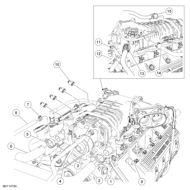
| Item
| Part Number
| Description
| | 1
| 15161
| Upper radiator hose clamp
|
| 2
| 8A586
| Upper radiator hose
|
| 3
| W527352
| Coolant vent hose clamp
|
| 4
| 8276
| Coolant vent hose
|
| 5
| 15161
| Upper radiator hose clamp
|
| 6
| 8A586
| Upper radiator hose
|
| 7
| W527352
| Coolant vent hose clamp
|
| 8
| 8276
| Coolant vent hose
|
| 9
| 14A464
| LH fuel injector electrical connector (4 required) (part of 12B637)
|
| 10
| 14A464
| RH fuel injector electrical connector (4 required) (part of 12B637)
|
| 11
| W527352
| Supercharger (SC) bubbler hose clamp (part of 6C324)
|
| 12
| 6C324
| bubbler hose
|
| 13
| 14A464
| EGR system module electrical connector (part of 12B637)
|
| 14
| 6K817
| Crankcase ventilation tube
|
| 15
| 14A464
| Fuel rail pressure and temperature sensor electrical connector (part of 12B637)
|
Throttle Body and Spacer Assembly
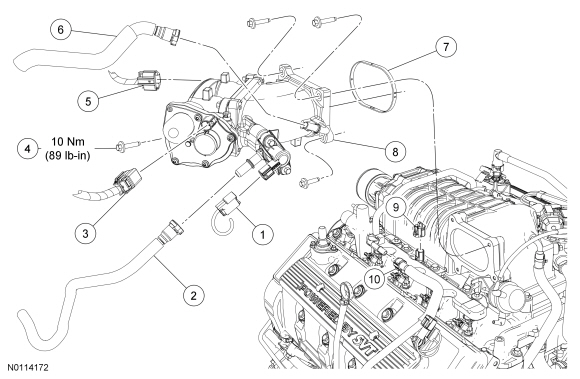
| Item
| Part Number
| Description
| | 1
| 14A464
| Evaporative Emission (EVAP) canister purge valve electrical connector (part of 12B637)
|
| 2
| 9G271
| canister purge valve vapor tube-to-Throttle Body (TB) spacer quick connect coupling
|
| 3
| 14A464
| Electronic throttle control electrical connector (part of 12B637)
|
| 4
| N806154
| spacer bolt (4 required)
|
| 5
| 14A464
| Throttle Position (TP) sensor electrical connector (part of 12B637)
|
| 6
| 2B432
| Brake booster-to-
spacer quick connect coupling
|
| 7
| 9L437
| spacer-to-Supercharger (SC) gasket
|
| 8
| 9E822
| spacer assembly
|
| 9
| 14A464
| Intake Air Temperature 2 (IAT2) sensor electrical connector (part of 12B637)
|
| 10
| 9J280
| Fuel supply tube-to-fuel rail quick connect coupling
|
Supercharger (SC) Drive Belt, Intake Manifold and Gaskets
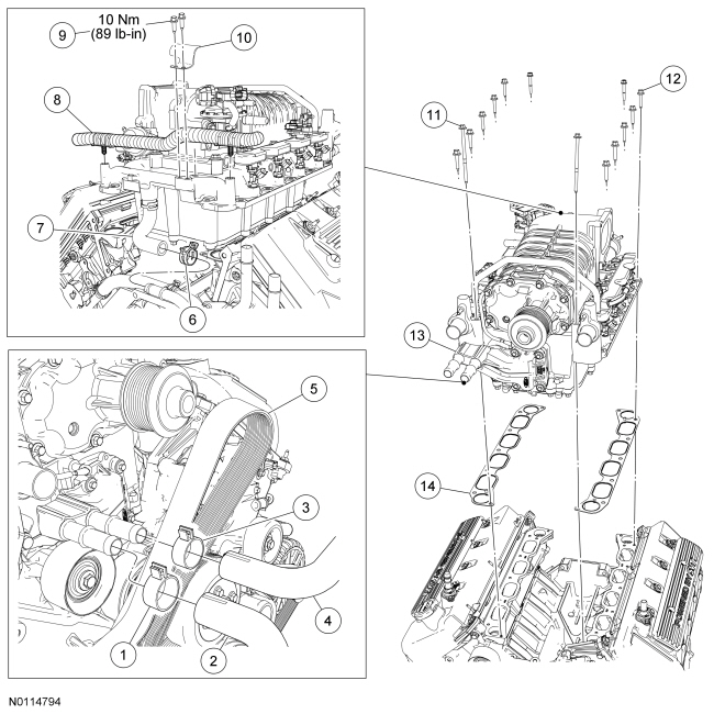
| Item
| Part Number
| Description
| | 1
| W527362
| Charge Air Cooler (CAC) hose clamp
|
| 2
| 8D030
| hose
|
| 3
| W527362
| hose clamp
|
| 4
| 8D031
| hose
|
| 5
| 8620
| drive belt
|
| 6
| 8287
| Heater hose clamp
|
| 7
| 18C553
| Heater hose
|
| 8
| —
| Wiring harness pin-type retainer (2 required) (part of 12B637)
|
| 9
| —
| Wiring harness retainer bolt (2 required)
|
| 10
| 14K060
| Wiring harness retainer
|
| 11
| W705654
| Intake manifold bolt (2 required)
|
| 12
| W704682
| Intake manifold bolt (12 required)
|
| 13
| 9H487
| Intake manifold
|
| 14
| 9439
| Intake manifold gasket (2 required)
|
Removal
 WARNING: Do not smoke, carry lighted tobacco or have an open flame of any type when working on or near any fuel-related component. Highly flammable mixtures are always present and may be ignited. Failure to follow these instructions may result in serious personal injury.
WARNING: Before working on or disconnecting any of the fuel tubes or fuel system components, relieve the fuel system pressure to prevent accidental spraying of fuel. Fuel in the fuel system remains under high pressure, even when the engine is not running. Failure to follow this instruction may result in serious personal injury.
NOTICE:
During engine repair procedures, cleanliness is extremely important. Any foreign material, including any material created while cleaning gasket surfaces that enters the oil passages, coolant passages or the oil pan, can cause engine failure.
- Release the fuel system pressure. Refer to
Section 310-00
.
- Drain the engine cooling system. Refer to
Section 303-03A
.
- Drain the Supercharger (SC) cooling system. Refer to
Section 303-03B
.
- Remove the Air Cleaner (ACL) outlet pipe. Refer to
Section 303-12
.
- Disconnect the battery ground cable. Refer to
Section 414-01
.
- Remove the EGR tube. Refer to
Section 303-08
.
- Disconnect the Throttle Position (TP) sensor electrical connector.
- Disconnect the Evaporative Emission (EVAP) tube and electrical connector from the
canister purge valve and the brake booster vacuum supply tube from the Throttle Body (TB) spacer.
- Remove the 4 bolts and the
and spacer assembly aside.
- Disconnect the Intake Air Temperature 2 (IAT2) sensor electrical connector.
- Disconnect the fuel supply tube. For additional information, refer to
Section 310-00
.
- Disconnect the 4 LH fuel injector electrical connectors.
- Remove the 2 bolts and the wiring harness retainer from the rear of the intake manifold.
- Detach the 2 wiring harness pin-type retainers from the rear of the intake manifold.
- Disconnect the fuel rail pressure and temperature sensor electrical connector.
- Disconnect the 4 RH fuel injector electrical connectors.
- Disconnect the EGR system module electrical connector.
- Disconnect the crankcase ventilation tube from the RH side of the
.
- Disconnect the
bubbler hose from the rear of the
.
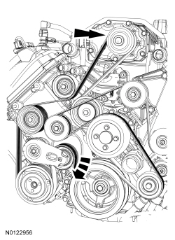
- Rotate the
drive belt tensioner clockwise and remove the drive belt from the
drive pulley.
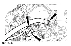
- Disconnect the 2 upper radiator hoses and the 2 coolant vent hoses from the intake manifold.
- Disconnect the 2 coolant hoses from the Charge Air Cooler (CAC).
- Disconnect the heater hose located below the rear of the intake manifold.
- Remove the 14 bolts and the intake manifold assembly.
Installation
NOTICE:
If the engine is repaired or replaced because of upper engine failure, typically including valve or piston damage, check the intake manifold for metal debris. If metal debris is found, install a new intake manifold. Failure to follow these instructions can result in engine damage.
NOTE:
Clean the sealing surfaces with metal surface prep. Follow the directions on the packaging. Inspect the mating surfaces.
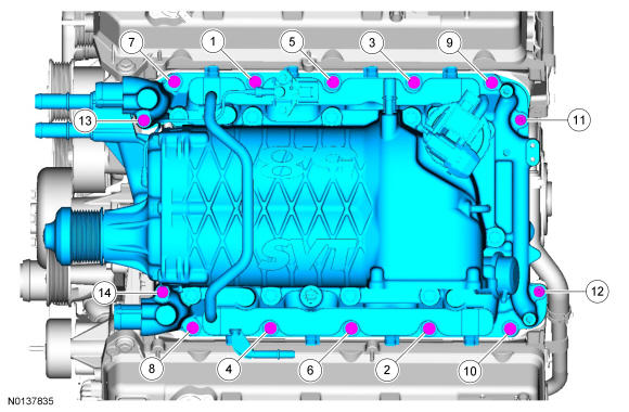
Using new intake manifold gaskets, position the intake manifold and install the 14 bolts. Tighten in the sequence shown.
- Tighten to 10 Nm (89 lb-in).
- Connect the heater hose located below the rear of the intake manifold.
- Connect the 2 coolant hoses to the
.
- Connect the 2 upper radiator hoses and the 2 coolant vent hoses to the intake manifold.
- Rotate the
drive belt tensioner clockwise and install the drive belt onto the
drive pulley.
- Connect the
bubbler hose to the rear of the
.
- Connect the crankcase ventilation tube to the RH side of the
.
- Connect the EGR system module electrical connector.
- Connect the 4 RH fuel injector electrical connectors.
- Connect the fuel rail pressure and temperature sensor electrical connector.
- Attach the 2 wiring harness pin-type retainers to the rear of the intake manifold.
- Install the wiring harness retainer and the 2 bolts onto the rear of the intake manifold.
- Tighten to 10 Nm (89 lb-in).
- Connect the 4 LH fuel injector electrical connectors.
- Connect the fuel supply tube. For additional information, refer to
Section 310-00
.
- Connect the
sensor electrical connector.
- Install the
and spacer assembly and the 4 bolts.
- Tighten to 10 Nm (89 lb-in).
- Connect the
tube and electrical connector from the
canister purge valve and the brake booster vacuum supply tube from the
spacer.
- Connect the
sensor electrical connector.
- Install the EGR tube. Refer to
Section 303-08
.
- Install the
outlet pipe. Refer to
Section 303-12
.
- Connect the battery ground cable. Refer to
Section 414-01
.
- Fill and bleed the
cooling system. Refer to
Section 303-03B
.
- Fill and bleed the engine cooling system. Refer to
Section 303-03A
.