
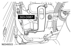
303-D087 (D93P-6001-A1) or equivalent

303-F070

303-F072
SECTION 303-01C: Engine — 5.8L (4V)
| 2014 Mustang Workshop Manual
|
IN-VEHICLE REPAIR
| Procedure revision date: 01/07/2013
|
| Lifting Bracket, Engine (2 required)
303-D087 (D93P-6001-A1) or equivalent |
| Support Bar, Engine
303-F070 |
| Support Bar, Engine
303-F072 |
| Item | Specification |
|---|---|
| Motorcraft® High Performance Engine RTV Silicone
TA-357 | WSE-M4G323-A6 |
| Motorcraft® Metal Surface Prep
ZC-31-A | — |
| Motorcraft® SAE 5W-50 Full Synthetic Motor Oil
XO-5W50-QGT | WSS-M2C931-B |
| Motorcraft® Silicone Gasket Remover
ZC-30 | — |
Removal
NOTICE: During engine repair procedures, cleanliness is extremely important. Any foreign material, including any material created while cleaning gasket surfaces, that enters the oil passages, coolant passages or the oil pan, can cause engine failure.
NOTE: Use a steering wheel holding device (such as Hunter® 28-75-1 or equivalent).
Using a suitable holding device, hold the steering wheel in the straight-ahead position.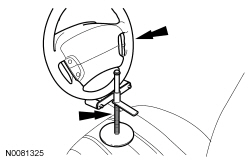
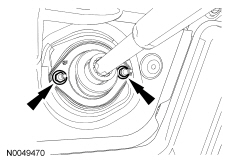
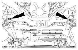
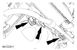
NOTE: LH side shown, RH side similar.
Remove the LH and RH engine support insulator nuts.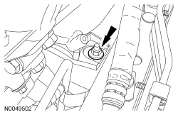
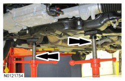
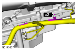
NOTE: The heavy duty Engine Support Bar (303-F070) must be used with the draw screws from the light duty Engine Support Bar (303-F072). This will provide enough clearance between the Supercharger (SC) and the Engine Support Bar, and enough clearance between the draw screw and the vehicle hood.
Install the Engine Support Bars and raise the engine.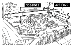

NOTICE: Do not allow the steering wheel to rotate while the steering column intermediate shaft is disconnected or damage to the clockspring can result. If there is evidence that the wheel has rotated, the clockspring must be removed and recentered. For additional information, refer to Section 501-20B .
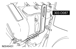
Remove the upper bolt from the intermediate steering shaft.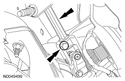
NOTE: LH side shown, RH side similar.
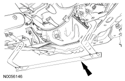
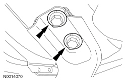
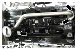
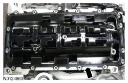
Remove the 2 lower bellhousing stud bolts.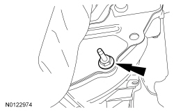
Installation
NOTICE: Do not use metal scrapers, wire brushes, power abrasive discs or other abrasive means to clean the sealing surfaces. These tools cause scratches and gouges which make leak paths. Use a plastic scraping tool to remove all traces of old sealant.
NOTE: Clean the sealing surfaces with silicone gasket remover and metal surface prep. Follow the directions on the packaging. Failure to follow this procedure can cause future oil leakage.
Clean and inspect the mating surfaces of the engine block and oil pan.NOTICE: Failure to use Motorcraft® High Performance Engine RTV Silicone may cause the engine oil to foam excessively and result in serious engine damage.
NOTE: If the oil pan is not installed and the fasteners tightened within 4 minutes, the sealant must be removed and the sealing area cleaned. To clean the sealing area, use silicone gasket remover and metal surface prep. Failure to follow this procedure can cause future oil leakage. If this timing cannot be met, tighten fasteners 7, 8, 9 and 10 to 8 Nm (71 lb-in) within 4 minutes of applying the sealer and final torque all of the fasteners within 1 hour of applying the sealer.
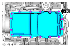
Apply an 8 mm (0.31 in) bead of Motorcraft® High Performance Engine RTV Silicone to the crankshaft rear seal retainer plate-to-cylinder block sealing surfaces and the engine front cover-to-cylinder block sealing surfaces.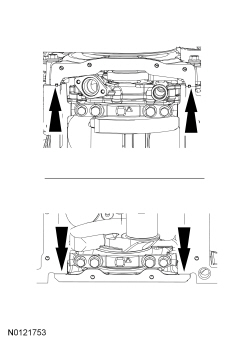
NOTE: The 2 oil pump screen and pickup tube-to-oil pump bolts must be tightened prior to tightening the oil pump screen and pickup tube-to-spacer bolt.
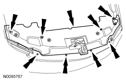
Using a new O-ring seal, install the oil pump screen and pickup tube and the 3 bolts. Tighten the 2 oil pump screen and pickup tube-to-oil pump bolts.NOTE: Fastener locations 11, 12 and 13 are stud bolts.
Install the oil pan, 13 bolts and 3 stud bolts. Tighten in the sequence shown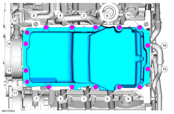
NOTE: LH side shown, RH side similar.
Install the 2 lower bellhousing stud bolts.NOTICE: Do not allow the steering wheel to rotate while the steering column intermediate shaft is disconnected or damage to the clockspring can result. If there is evidence that the wheel has rotated, the clockspring must be removed and recentered. For additional information, refer to Section 501-20B .
Position the intermediate steering shaft and install the upper bolt.NOTE: Do not tighten the subframe nuts and bolts at this time.
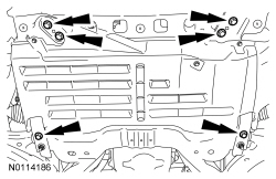
Install the 4 subframe nuts and 4 subframe bolts.NOTICE: Do not tighten the engine support insulator nuts until the full weight of the engine is on the engine insulator or damage to the engine insulator may occur.
NOTE: LH side shown, RH side similar.
Install the LH and RH engine support insulator nuts.