SECTION 303-01C: Engine — 5.8L (4V)
| 2014 Mustang Workshop Manual
|
IN-VEHICLE REPAIR
| Procedure revision date: 01/07/2013
|
| Item | Specification |
|---|---|
| Motorcraft® High Performance Engine RTV Silicone
TA-357 | WSE-M4G323-A6 |
| Motorcraft® Metal Surface Prep
ZC-31-A | — |
| Motorcraft® Silicone Gasket Remover
ZC-30 | — |
| Item | Part Number | Description |
|---|---|---|
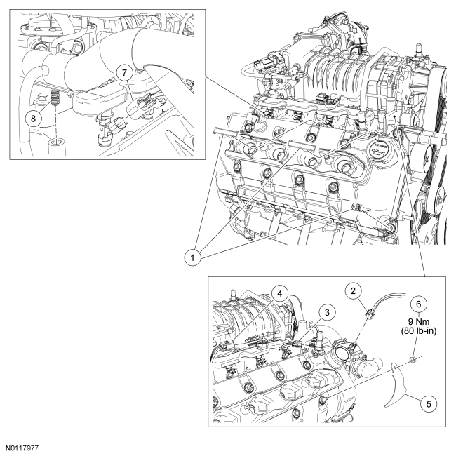
| 1 | — | Wiring harness retainers (3 required) (part of 12B637) |
| 2 | 14A464 | Engine Coolant Temperature (ECT) sensor electrical connector (part of 12B637) |
| 3 | 14A464 | PCV valve electrical connector (part of 12B637) |
| 4 | 14A464 | Fuel rail pressure and temperature sensor electrical connector (part of 12B637) |
| 5 | 19C789 | A/C tube support bracket |
| 6 | W520111 | A/C tube support bracket nut |
| 7 | 14A464 | RH fuel injector electrical connector (4 required) (part of 12B637) |
| 8 | — | Wiring harness retainer (part of 12B637) |
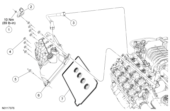
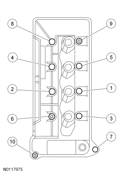
| Item | Part Number | Description |
|---|---|---|
| 1 | W520111 | RH radio interference capacitor nut |
| 2 | 18801 | RH radio interference capacitor |
| 3 | 64817 | Crankcase ventilation hose |
| 4 | W708441 | RH valve cover bolt (7 required) |
| 5 | W708442 | RH valve cover stud bolt (3 required) |
| 6 | 6582 | RH valve cover assembly |
| 7 | 6584 | RH valve cover gaskets |
Removal
NOTICE: Do not use metal scrapers, wire brushes, power abrasive discs or other abrasive means to clean the sealing surfaces. These tools cause scratches and gouges which make leak paths. Use a plastic scraping tool to remove all traces of old sealant.
Clean the mating surfaces with silicone gasket remover and metal surface prep. Follow the directions on the packaging.Installation
NOTE: If the valve cover is not secured within 4 minutes, the sealant must be removed and the sealing area cleaned with metal surface prep. Allow to dry until there is no sign of wetness, or 4 minutes, whichever is longer. Failure to follow this procedure can result in future oil leakage.
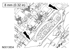
Apply a bead of Motorcraft® High Performance Engine RTV Silicone in 2 places where the engine front cover meets the cylinder head.