SECTION 303-01C: Engine — 5.8L (4V)
| 2014 Mustang Workshop Manual
|
REMOVAL
| Procedure revision date: 01/07/2013
|
Engine
Special Tool(s)
 | 2,200# Floor Crane, Fold Away
300-OTC1819E or equivalent
|
 | Lifting Bracket, Engine (2 required)
303-D087 (D93P-6001-A1) or equivalent
|
 | Lifting Bracket, Engine
303-D089 (D93P-6001-A3) or equivalent
|
 WARNING: Do not smoke, carry lighted tobacco or have an open flame of any type when working on or near any fuel-related component. Highly flammable mixtures are always present and may be ignited. Failure to follow these instructions may result in serious personal injury.
WARNING: Before working on or disconnecting any of the fuel tubes or fuel system components, relieve the fuel system pressure to prevent accidental spraying of fuel. Fuel in the fuel system remains under high pressure, even when the engine is not running. Failure to follow this instruction may result in serious personal injury.
WARNING: Do not breathe dust or use compressed air to blow dust from storage containers or friction components. Remove dust using government-approved techniques. Friction component dust may be a cancer and lung disease hazard. Exposure to potentially hazardous components may occur if dusts are created during repair of friction components, such as brake pads and clutch discs. Exposure may also cause irritation to skin, eyes and respiratory tract, and may cause allergic reactions and/or may lead to other chronic health effects. If irritation persists, seek medical attention or advice. Failure to follow these instructions may result in serious personal injury.
All vehicles
- With the vehicle in NEUTRAL, position it on a hoist. Refer to
Section 100-02
.
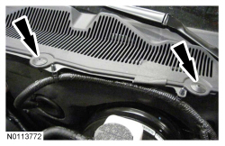
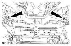
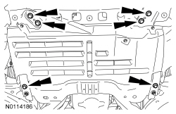
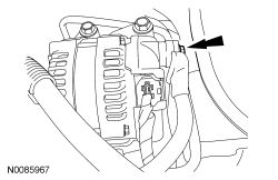
- Release the 2 windshield washer hose retainers and the 8 hood insulation pin-type retainers (2 shown).
- Detach the 2 windshield washer hose retainers and disconnect the 2 windshield washer hose C-Lock Couplers. Refer to
Section 501-16
.
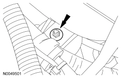
NOTE:
Index-mark the hood hinge location to aid in hood installation.
NOTE:
RH shown, LH similar.
Remove the 4 bolts (2 shown) and the hood.
- Release the fuel system pressure. Refer to
Section 310-00
.
- Remove the battery and tray. Refer to
Section 414-01
.
- Remove the Air Cleaner (ACL) assembly and
outlet pipe. Refer to
Section 303-12
.
- Remove brake booster. Refer to
Section 206-07
.
- Drain the cooling system. Refer to
Section 303-03A
.
- Drain the Supercharger (SC) cooling system. Refer to
Section 303-03B
.
- Remove the engine coolant degas bottle. Refer to
Section 303-03A
.
- Remove the
coolant degas bottle. Refer to
Section 303-03B
.
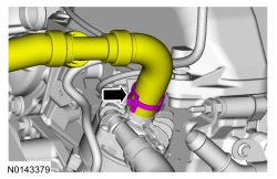
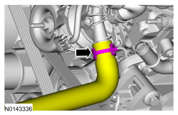
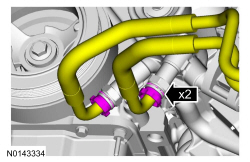
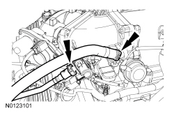
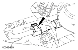
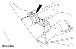
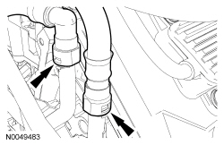
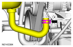
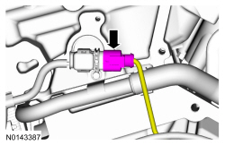
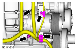
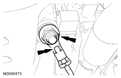
- Disconnect the upper coolant hose from the
coolant pump.
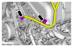
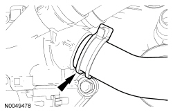
- Disconnect the lower coolant hose from the
coolant pump.
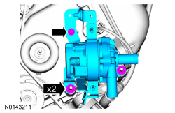
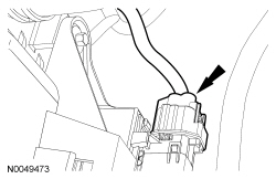
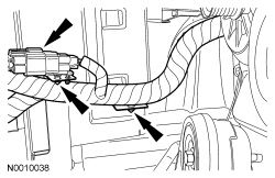
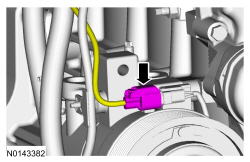
- Disconnect the
coolant pump electrical connector and retainer.
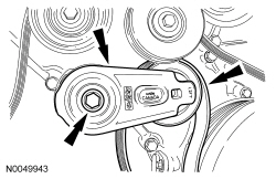
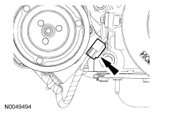
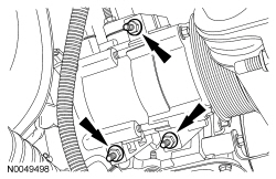
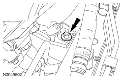
- Remove the 2 nuts, bolt and the
coolant pump.
Vehicle equipped with the cooling package
- Remove the 2 retaining clips and disconnect the 2 oil hoses from the oil filter adapter.
- Remove the bolt and position the transmission cooler hoses aside.
All vehicles
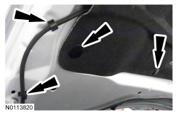
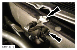
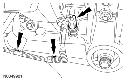
- Remove the 2 LH cowl vent screen plastic rivets.
- Lift the cowl screen and remove the ground strap bolt.
- Detach the wiring retainer from the cowl.
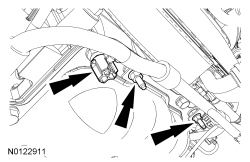
- Disconnect the Evaporative Emission (EVAP) tube and the brake booster vacuum supply tube from the Throttle Body (TB) spacer. Refer to
Section 310-00
.
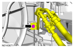
- Disconnect the fuel supply tube. Refer to
Section 310-00
.
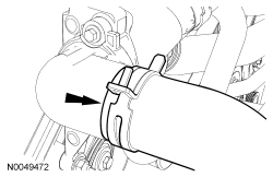
- Disconnect the upper radiator hose from the thermostat housing.
- Disconnect the cooling fan electrical connector.
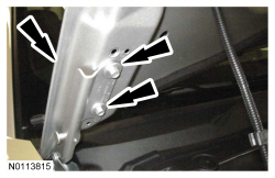
NOTE:
RH bolt shown, LH similar.
Remove the 2 bolts and the cooling fan assembly.
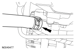
- Disconnect the coolant hose from the Charge Air Cooler (CAC).
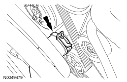
- Disconnect the coolant hose from the thermostat housing.
- Disconnect the coolant hose from the coolant tube assembly (above the generator).
- Disconnect the coolant hose from the coolant pump.
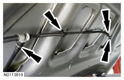
- Disconnect the 2 heater hoses from the coolant tube assembly at the rear of the engine.
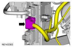
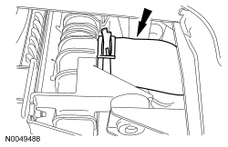
- Disconnect the 16-pin electrical connector and detach the 2 wiring retainers.
- Disconnect the PCM electrical connector.
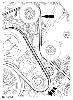
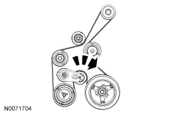
- Rotate the accessory drive belt tensioner clockwise and remove the accessory drive belt.
- Rotate the
drive belt tensioner clockwise and remove the drive belt from the
drive pulley.
- Remove the bolt,
drive belt tensioner and the
drive belt.
- If equipped, disconnect the coolant hose from the oil cooler.
- Disconnect the lower radiator hose from the radiator.
- Remove the lower radiator hose assembly from the vehicle.
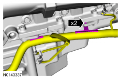
- Loosen the 2 crossmember brace nuts.
- Remove the 6 bolts and remove the crossmember brace.
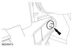
- Disconnect the LH Heated Oxygen Sensor (HO2S) electrical connector.
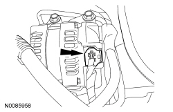
- Disconnect the generator electrical connector.
- Remove the nut and disconnect the B+ wire from the generator.
- Disconnect the Engine Oil Pressure (EOP) switch electrical connector and the 2 wire retainers.
- Detach the wire retainer. Remove the 2 nuts and the 2 wire harness brackets from the oil pan studs.
- Detach the 2 wire harness retainers from the oil pan.
- Disconnect the A/C compressor electrical connector.
- Disconnect the Crankshaft Position (CKP) sensor electrical connector.
- Remove the nut and position out the engine wire harness retainers. Disconnect the retainer from the back of the A/C compressor.
- Remove the nut and position out the ground wire from the RH engine insulator.
- Remove the 3 stud bolts and position the A/C compressor aside.
- Drain the engine oil.
- Install the drain plug and tighten to 26 Nm (19 lb-ft).
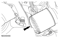
- Remove and discard the engine oil filter.
- Remove the clutch disc and pressure plate. Refer to
Section 308-01
.
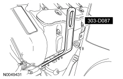
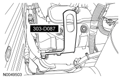
- Install the Engine Lifting Bracket.
- Install the Engine Lifting Bracket.
- Remove the RH engine support insulator nut.
- Remove the LH engine support insulator nut.
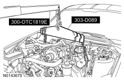
- Install the Floor Crane and the Engine Lifting Bracket.
- Remove the engine from the vehicle.