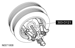
303-D121 or equivalent

303-452 (T93P-6565-AR)

303-442 (T93P-6136-A)

303-519 (T95P-6701-EH)

303-514 (T95P-6701-AH)

303-409 (T92C-6700-CH)

100-001 (T50T-100-A)

303-D055 (D85L-6000-A) or equivalent
SECTION 303-01C: Engine — 5.8L (4V)
| 2014 Mustang Workshop Manual
|
DISASSEMBLY
| Procedure revision date: 01/07/2013
|
| 3 Jaw Puller
303-D121 or equivalent |
| Compressor, Valve Spring
303-452 (T93P-6565-AR) |
| Installer, Connecting Rod
303-442 (T93P-6136-A) |
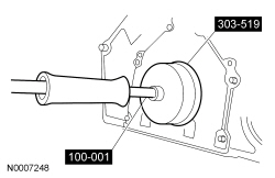
| Remover, Crankshaft Rear Oil Seal
303-519 (T95P-6701-EH) |
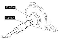
| Remover, Crankshaft Rear Oil Slinger
303-514 (T95P-6701-AH) |
| Remover, Oil Seal
303-409 (T92C-6700-CH) |
| Slide Hammer
100-001 (T50T-100-A) |
| Strap Wrench
303-D055 (D85L-6000-A) or equivalent |
| Item | Specification |
|---|---|
| Motorcraft® Metal Surface Prep
ZC-31-A | — |
| Motorcraft® Silicone Gasket Remover
ZC-30 | — |
NOTICE: Remove the cylinder heads before removing the crankshaft. Failure to do so can result in engine damage.
NOTICE: During engine repair procedures, cleanliness is extremely important. Any foreign material, including any material created while cleaning gasket surfaces that enters the oil passages, coolant passages or the oil pan, can cause engine failure.
NOTE: The flywheel, crankshaft rear oil slinger, crankshaft rear seal and crankshaft rear seal retainer plate must be removed before mounting the engine on the engine stand.
NOTE: For additional information, refer to the exploded view under the Assembly procedure in this section.
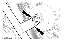
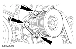
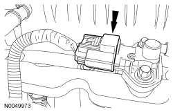
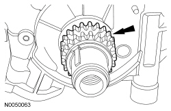
NOTICE: The flywheel is a press fit on the crankshaft pilot. Do not use screwdrivers or prybars to remove the flywheel or damage to the flywheel or engine may occur.
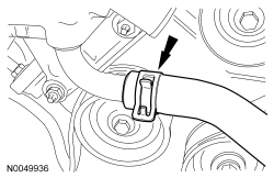
Remove the flywheel.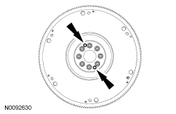
NOTICE: Do not use metal scrapers, wire brushes, power abrasive discs or other abrasive means to clean the sealing surfaces. These tools cause scratches and gouges which make leak paths. Use a plastic scraping tool to remove all traces of old sealant.
Clean the mating surfaces with silicone gasket remover and metal surface prep. Follow the directions on the packaging.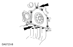

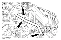
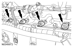

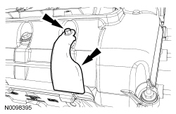
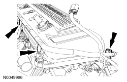
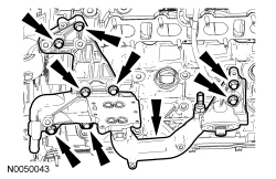
NOTICE: If the engine is repaired or replaced because of upper engine failure, typically including valve or piston damage, check the intake manifold for metal debris. If metal debris is found, install a new intake manifold. Failure to follow these instructions can result in engine damage.
Remove the 14 bolts and the intake manifold assembly.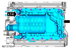
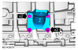

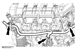
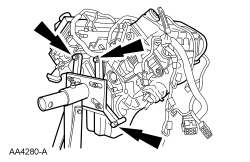
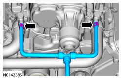
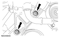
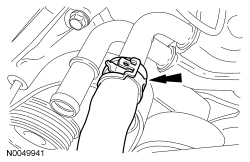
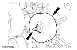
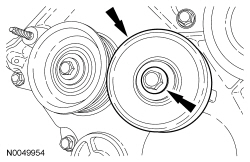
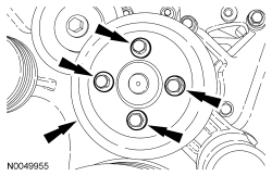
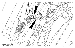
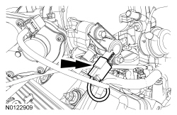
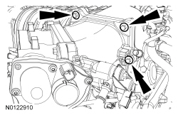
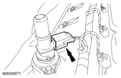
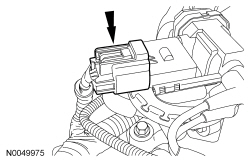
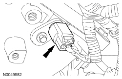
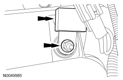
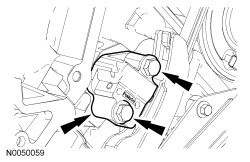
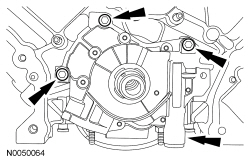
NOTICE: A new oil cooler and oil cooler thermostat (if equipped) must be installed or severe damage to the engine can occur.
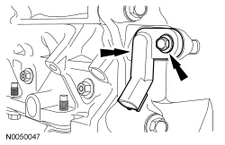
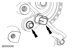
NOTE: Oil cooler shown, oil cooler thermostat similar.
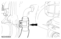
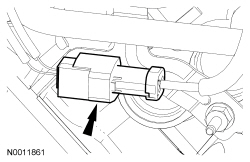
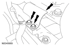
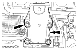
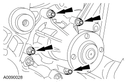
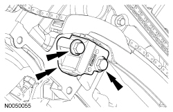
Remove the 6 bolts and the oil cooler or oil cooler thermostat.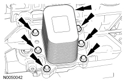
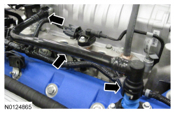
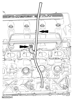
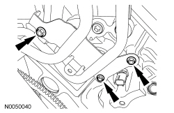
NOTICE: Do not use metal scrapers, wire brushes, power abrasive discs or other abrasive means to clean the sealing surfaces. These tools cause scratches and gouges which make leak paths. Use a plastic scraping tool to remove all traces of old sealant.
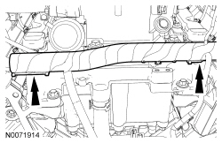
Remove the 13 bolts, 3 stud bolts and the oil pan.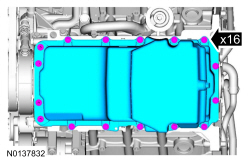
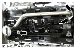
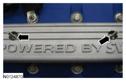
NOTICE: Do not use metal scrapers, wire brushes, power abrasive discs or other abrasive means to clean the sealing surfaces. These tools cause scratches and gouges which make leak paths. Use a plastic scraping tool to remove all traces of old sealant.
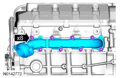
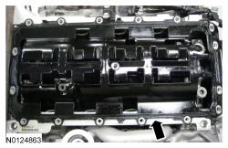
Remove the bolts, stud bolts and RH valve cover.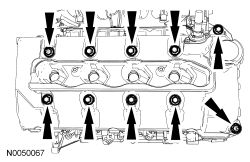
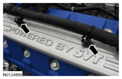
NOTICE: Do not use metal scrapers, wire brushes, power abrasive discs or other abrasive means to clean the sealing surfaces. These tools cause scratches and gouges which make leak paths. Use a plastic scraping tool to remove all traces of old sealant.
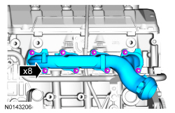
Remove the bolts, stud bolts and LH valve cover.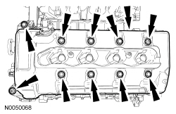
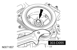
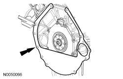
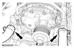
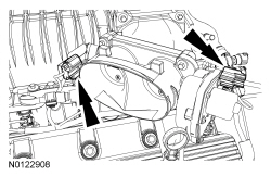
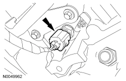
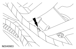
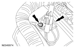
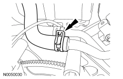
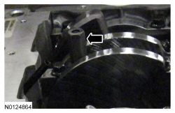
NOTICE: Use care not to damage the engine front cover or the crankshaft when removing the seal.
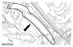
Using the Oil Seal Remover, remove the crankshaft front oil seal.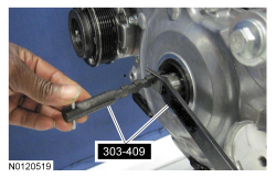
NOTICE: Do not use metal scrapers, wire brushes, power abrasive discs or other abrasive means to clean the sealing surfaces. These tools cause scratches and gouges which make leak paths. Use a plastic scraping tool to remove all traces of old sealant.
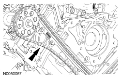
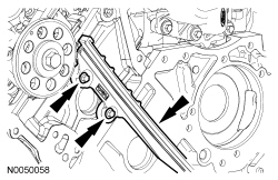
Remove the 16 bolts and the engine front cover.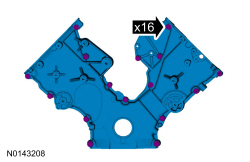
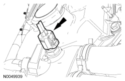
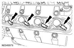
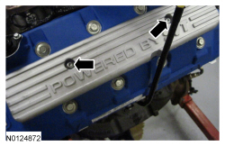
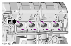
NOTICE: Only use hand tools when removing or installing the spark plugs, or damage may occur to the cylinder head or spark plugs.
NOTE: Use compressed air to remove any foreign material in the spark plug well before removing the spark plugs.
NOTE: RH shown, LH similar.
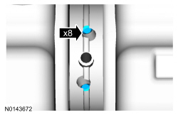
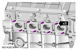
Remove the 8 spark plugs.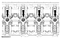
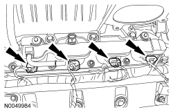
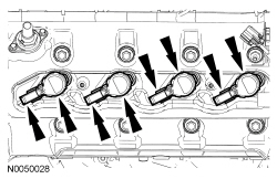
NOTICE: If the components are to be reinstalled, they must be installed in their original positions. Mark the components for installation into their original locations. Failure to follow these instructions may result in engine damage.
Using the Valve Spring Compressor, compress the valve spring and remove the roller follower.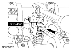
NOTICE: If the components are to be reinstalled, they must be installed in their original positions. Mark the components for installation into their original locations. Failure to follow these instructions may result in engine damage.
Remove the hydraulic lash adjusters.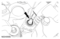
NOTICE: The cylinder head must be cool before removing it from the engine. Cylinder head warpage can result if a warm or hot cylinder head is removed.
NOTICE: Place clean shop towels over exposed engine cavities. Carefully remove the towels so foreign material is not dropped into the engine.
NOTICE: The cylinder head bolts must be discarded and new bolts must be installed. They are a tighten-to-yield design and cannot be reused.
NOTICE: Do not use metal scrapers, wire brushes, power abrasive discs or other abrasive means to clean the sealing surfaces. These tools cause scratches and gouges that make leak paths. Use a plastic scraping tool to remove all traces of the head gasket.
NOTICE: Aluminum surfaces are soft and can be scratched easily. Never place the cylinder head gasket surface, unprotected, on a bench surface.
NOTE: LH shown, RH similar.
Remove the bolts, the RH cylinder head and the LH cylinder head.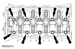
NOTICE: Do not use metal scrapers, wire brushes, power abrasive discs or other abrasive means to clean the sealing surfaces. These tools cause scratches and gouges that make leak paths. Use a plastic scraping tool to remove all traces of the head gasket.
NOTE: Observe all warnings or cautions and follow all application directions contained on the packaging of the silicone gasket remover and the metal surface prep.
NOTE: If there is no residual gasket material present, metal surface prep can be used to clean and prepare the surfaces.
Clean the cylinder head-to-cylinder block mating surfaces of both the cylinder head and the cylinder block in the following sequence.NOTE: Make sure all cylinder head surfaces are clear of any gasket material, RTV, oil and coolant. The cylinder head surface must be clean and dry before running a flatness check.
NOTE: Use a straightedge that is calibrated by the manufacturer to be flat within 0.005 mm (0.0002 in) per running foot length. For example, if the straightedge is 61 cm (24 in) long, the machine edge must be flat within 0.010 mm (0.0004 in) from end to end.
NOTE: LH shown, RH similar.
Support the cylinder heads on a bench with the head gasket side up. Check the cylinder head distortion and the cylinder block distortion, paying particular attention to the oil pressure feed area. Refer to Section 303-00 .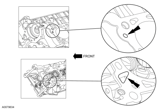
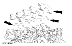
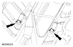
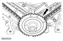
NOTE: Verify that the connecting rods and rod caps have orientation numbers cast into them. If not, number the connecting rods and rod caps for correct orientation.
Remove the bolts and the connecting rod caps for pistons No. 1 and No. 6.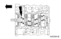
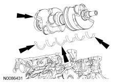
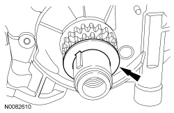
NOTICE: Do not scratch the cylinder walls or crankshaft journals with the connecting rod.
Using the Connecting Rod Installer, push pistons 1 and 6 through the top of the cylinder block.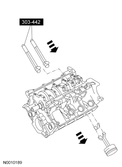
NOTICE: Remove the cylinder heads before removing the crankshaft. Failure to do so can result in engine damage.
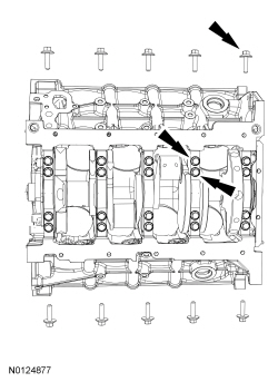
Remove and discard the crankshaft main bearing cap bolts.