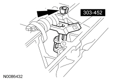
303-452 (T93P-6565-AR)

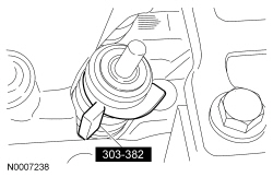
303-382 (T91P-6565-AH)

303-446 (T93P-6256-AHR)

303-383 (T91P-6571-A)
SECTION 303-01C: Engine — 5.8L (4V)
| 2014 Mustang Workshop Manual
|
DISASSEMBLY AND ASSEMBLY OF SUBASSEMBLIES
| Procedure revision date: 01/07/2013
|
| Compressor, Valve Spring
303-452 (T93P-6565-AR) |
| Compressor Spacer, Valve Spring
303-382 (T91P-6565-AH) |
| Holding Tool, Camshaft
303-446 (T93P-6256-AHR) |
| Installer, Valve Stem Oil Seal
303-383 (T91P-6571-A) |
| Item | Specification |
|---|---|
| Motorcraft® SAE 5W-50 Full Synthetic Motor Oil
XO-5W50-QGT | WSS-M2C931-B |
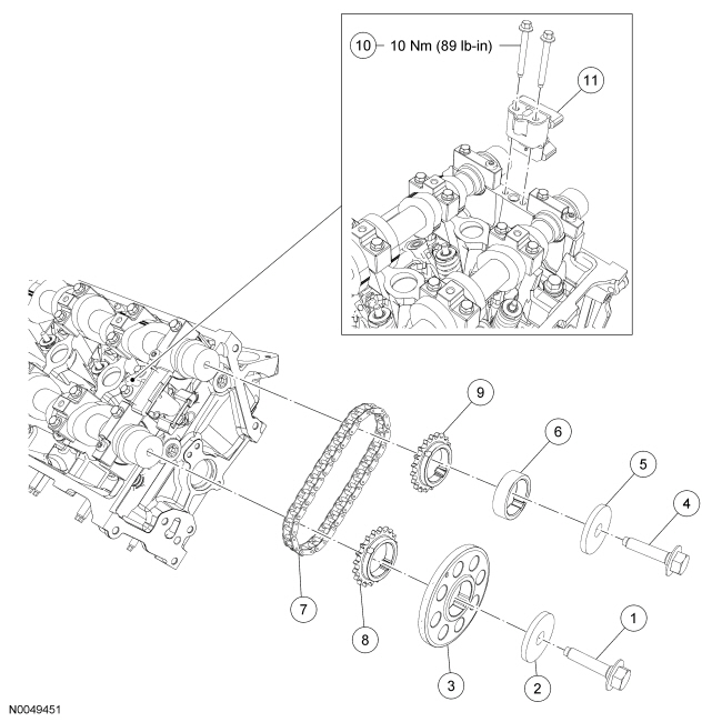
| Item | Part Number | Description |
|---|---|---|
| 1 | N811085 | Camshaft drive sprocket bolt |
| 2 | N806164 | Camshaft drive sprocket washer |
| 3 | 6C252 RH/ 6C253 LH | Camshaft drive sprocket |
| 4 | N811085 | Camshaft drive sprocket bolt |
| 5 | N806164 | Camshaft drive sprocket washer |
| 6 | 6265 | Camshaft drive sprocket spacer |
| 7 | 6268 | Secondary timing chain |
| 8 | 6256 | Exhaust camshaft drive sprocket |
| 9 | 6256 | Intake camshaft drive sprocket |
| 10 | W500304 RH/ W500215 LH | Secondary timing chain tensioner bolt (2 required) |
| 11 | 6C270 RH/ 6C271 LH | Secondary timing chain tensioner |
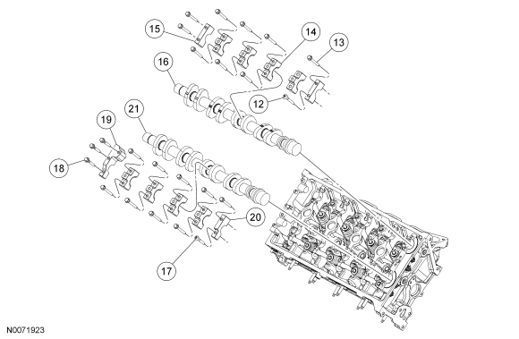
| Item | Part Number | Description |
|---|---|---|
| 12 | W710990 | Intake camshaft bearing cap bolt |
| 13 | N807352 | Intake/exhaust camshaft bearing cap bolt (22 required) |
| 14 | 6B277 | Intake/exhaust camshaft bearing cap (8 required) |
| 15 | 6B277 | Intake camshaft bearing cap (2 required) |
| 16 | 6A270 RH/ 6A271 LH | Intake camshaft |
| 17 | W710991 | Exhaust camshaft bearing cap bolt |
| 18 | W705438 | Exhaust camshaft bearing cap bolt |
| 19 | 6B278 | Exhaust camshaft bearing cap |
| 20 | 6B278 | Exhaust camshaft bearing cap |
| 21 | 6A272 RH/ 6A273 LH | Exhaust camshaft |
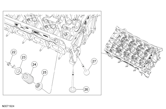
| Item | Part Number | Description |
|---|---|---|
| 22 | 6518 | Retainer key (32 required) |
| 23 | 6514 | Valve spring retainer (16 required) |
| 24 | 6513 | Valve spring |
| 25 | 6A517 | Valve seal |
| 26 | 6507 | Intake valve |
| 27 | 6505 | Exhaust valve |
Disassembly
NOTICE: Before disassembly begins, mark the valve position on the face of each valve being removed. The valves must be reinstalled into their original positions or damage to the engine may occur.
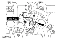
Install the Camshaft Holding Tool.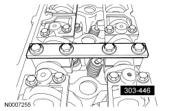
NOTE: RH shown, LH similar.
Remove the bolt, washer and camshaft drive sprocket.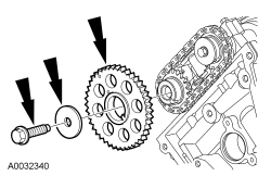
NOTE: RH shown, LH similar.
Remove the bolt, washer and spacer.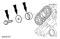
NOTE: LH shown, RH similar.
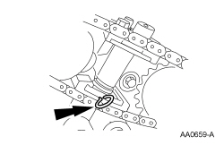
Remove the timing chain and the 2 camshaft sprockets.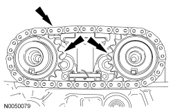
NOTE: LH shown, RH similar.
Remove the 2 bolts and the secondary timing chain tensioner.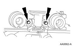
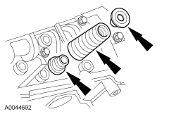
NOTICE: The camshaft bearing cap bolts vary in length and head design and must be installed in their original positions. Camshaft bearing caps are not interchangeable and must be installed in their original positions or damage to the engine may occur.
NOTE: The camshaft bearing cap with 3 bolts is located at the front of the LH cylinder head and at the rear of the RH cylinder head.
Remove the camshaft bearing cap bolts in the sequence shown.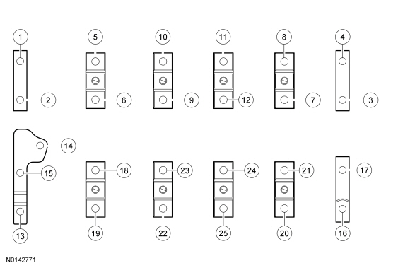
Assembly
NOTE: Lubricate the camshafts with clean engine oil prior to installation.
NOTE: RH shown, LH similar.
Install the camshafts.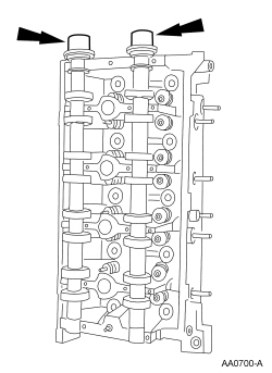
NOTICE: The camshaft bearing cap bolts vary in length and head design and must be installed in their original positions. Camshaft bearing caps are not interchangeable and must be installed in their original positions or damage to the engine may occur.
NOTE: The camshaft bearing cap with 3 bolts is located at the front of the LH cylinder head and at the rear of the RH cylinder head.
NOTE: Lubricate the camshaft bearing cap bearing surfaces with clean engine oil prior to installation.
Install the camshaft bearing caps and bearing cap bolts. Tighten in the sequence shown in 2 stages.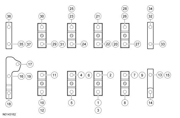
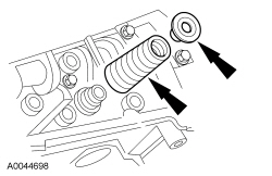
NOTE: Lubricate the valve seal and valve stem with clean engine oil prior to installation.
Using the Valve Stem Oil Seal Installer and the Valve Spring Compressor, install a new valve seal.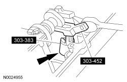
NOTE: LH shown, RH similar.
Install the secondary timing chain tensioner and the bolts.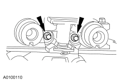
NOTE: LH shown, RH similar.
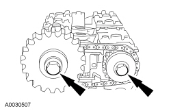
Index the keyways on the camshafts to the 6 o'clock position.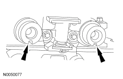
NOTICE: Timing marks must be at the 12 o'clock position or damage to the engine may occur.
NOTE: LH shown, RH similar.
Install the camshaft sprockets and the chain as an assembly.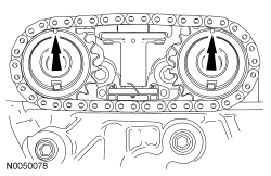
NOTE: RH shown, LH similar.
Install the camshaft spacer, washer and bolt, and hand-tighten the bolt.NOTE: RH shown, LH similar.
Install the camshaft sprocket, washer and bolt, and hand-tighten the bolt.NOTE: RH shown, LH similar.
Tighten the bolts in 2 stages: