SECTION 303-01C: Engine — 5.8L (4V)
| 2014 Mustang Workshop Manual
|
DISASSEMBLY AND ASSEMBLY OF SUBASSEMBLIES
| Procedure revision date: 01/07/2013
|
| Item | Specification |
|---|---|
| Motorcraft® Orange Antifreeze/Coolant Concentrated
VC-3-B (US); CVC-3-B2 (Canada) | WSS-M97B44-D |
| Motorcraft® SAE 5W-50 Full Synthetic Motor Oil
XO-5W50-QGT | WSS-M2C931-B |
| Motorcraft® Threadlock and Sealer
TA-25 | WSK-M2G351-A5 |
| Item | Part Number | Description |
|---|---|---|
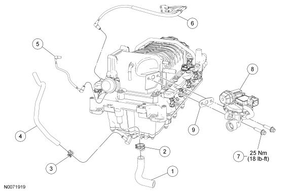
| 1 | 18C553 | Heater hose |
| 2 | — | Heater hose clamp (part of 18C553) |
| 3 | W527352 | Supercharger (SC) bubbler hose clamp |
| 4 | 6C324 | SC bubbler hose |
| 5 | 9E498 | Lower SC bypass actuator vacuum tube |
| 6 | 9E498 | Upper SC bypass actuator vacuum tube |
| 7 | W701232 | EGR system module bolt (2 required) |
| 8 | 9Y456 | EGR system module |
| 9 | 9D476 | EGR system module gasket |
| Item | Part Number | Description |
|---|---|---|
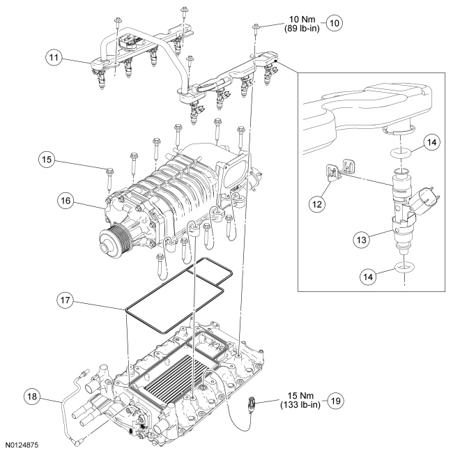
| 10 | N804394 | Fuel rail bolt (4 required) |
| 11 | 9F792 | Fuel rail |
| 12 | 9F907 | Fuel injector clip (8 required) |
| 13 | 9F593 | Fuel injector (8 required) |
| 14 | 9229 | Fuel injector O-ring (16 required) |
| 15 | N806177 | SC bolt (10 required) |
| 16 | 6F066 | SC |
| 17 | 9H486 | SC gasket |
| 18 | 9E498 | Fuel rail and pressure and temperature sensor vacuum tube |
| 19 | 12A697 | Intake Air Temperature 2 (IAT2) sensor |
| Item | Part Number | Description |
|---|---|---|
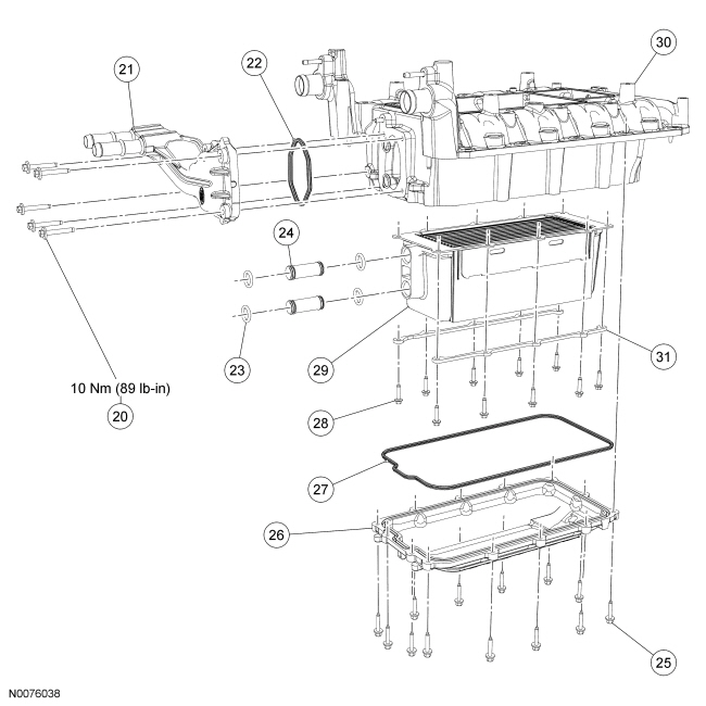
| 20 | N807071 | Charge Air Cooler (CAC) coolant tube assembly bolt (5 required) |
| 21 | 9N491 | CAC coolant tube assembly |
| 22 | 9L438 | CAC coolant tube assembly gasket |
| 23 | N802927 | CAC tube O-ring seal (4 required) |
| 24 | 9L442 | CAC coolant connector tube (2 required) |
| 25 | W704682 | Lower intake manifold cover bolt (13 required) |
| 26 | 9S455 | Lower intake manifold cover |
| 27 | 9E436 | Lower intake manifold cover gasket |
| 28 | N605893 | CAC bolt (10 required) |
| 29 | 6K775 | CAC |
| 30 | 9424 | Upper intake manifold |
| 31 | 6K808 | CAC rail support (2 required) |
Disassembly
NOTICE: Use O-ring seals that are made of special fuel-resistant material. Use of ordinary O-ring seals can cause the fuel system to leak. Do not reuse the O-ring seals.
Remove and discard the 16 fuel injector O-ring seals.Assembly
NOTICE: If the engine is repaired or replaced because of upper engine failure, typically including valve or piston damage, check the intake manifold for metal debris. If metal debris is found, install a new intake manifold. Failure to follow these instructions can result in engine damage.
NOTE: Apply threadlock and sealer to the CAC bolts prior to installation.
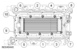
Position the CAC , the 2 CAC rail supports and install the 10 bolts. Tighten in the sequence shown in 2 stages.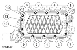
NOTE: Apply clean engine coolant to the new CAC coolant connector tube O-ring seals.
Install new O-ring seals on the CAC coolant connector tubes.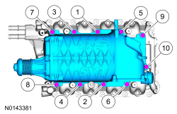
NOTE: Lubricate the new O-ring seal with clean engine oil prior to installation.
Install new O-ring seals on each of the fuel injectors.