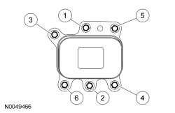
| Item
| Part Number
| Description
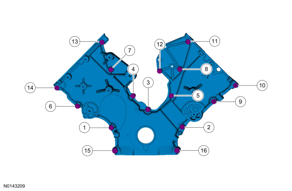
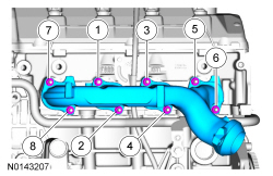
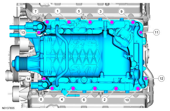
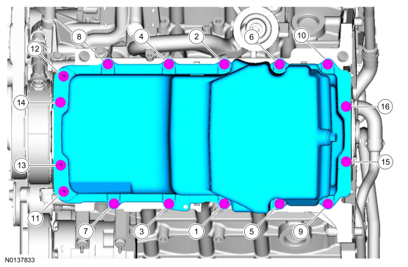
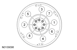
| | 1
| N806177
| Bolt, hex head pilot, M8 x 1.25 x 53
|
| 2
| N806177
| Bolt, hex head pilot, M8 x 1.25 x 53
|
| 3
| N806177
| Bolt, hex head pilot, M8 x 1.25 x 53
|
| 4
| N806177
| Bolt, hex head pilot, M8 x 1.25 x 53
|
| 5
| N806177
| Bolt, hex head pilot, M8 x 1.25 x 53
|
| 6
| N806177
| Bolt, hex head pilot, M8 x 1.25 x 53
|
| 7
| N806177
| Bolt, hex head pilot, M8 x 1.25 x 53
|
| 8
| N806177
| Bolt, hex head pilot, M8 x 1.25 x 53
|
| 9
| N808586
| Stud bolt, hex head pilot, M8 x 1.25 x 50
|
| 10
| N808586
| Stud bolt, hex head pilot, M8 x 1.25 x 50
|
| 11
| N806177
| Bolt, hex head pilot, M8 x 1.25 x 53
|
| 12
| N806177
| Bolt, hex head pilot, M8 x 1.25 x 53
|
| 13
| N806177
| Bolt, hex head pilot, M8 x 1.25 x 53
|
| 14
| N806177
| Bolt, hex head pilot, M8 x 1.25 x 53
|
| 15
| N606063
| Bolt, hex flange head pilot, M10 x 1.50 x 55
|
| 16
| N606063
| Bolt, hex flange head pilot, M10 x 1.50 x 55
|