SECTION 303-03A: Engine Cooling
| 2014 Mustang Workshop Manual
|
DESCRIPTION AND OPERATION
| Procedure revision date: 01/07/2013
|
NOTICE: The engine cooling system is filled with Motorcraft® Orange Antifreeze/Coolant. Always fill the cooling system with the manufacturer's specified coolant. Chemically flush the cooling system if a non-specified coolant has been used. Refer to Cooling System Flushing in this section. Failure to follow these instructions may damage the engine or cooling system.
NOTE: During normal vehicle operation, Motorcraft® Orange Antifreeze/Coolant may change color from orange to pink or light red. As long as the engine coolant is clear and uncontaminated, this color change does not indicate the engine coolant has degraded nor does it require the engine coolant to be drained, the system to be flushed, or the engine coolant to be replaced.
The cooling system components include the:
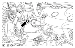
The 3.7L engine has a channel cover plate located under the engine front cover mounted to the block and has 2 press-in-place gaskets. A weep hole is provided on the front left side of the engine behind the generator. If oil or coolant leaks from this weep hole, the channel cover plate gaskets are leaking and new gaskets must be installed. Refer to Section 303-01A .
The 3.7L and 5.0L engines use a cold side thermostat. This means the thermostat controls the flow of cooled radiator coolant into the warmer engine cooling circuit. The thermostat is located at the lower radiator hose connection to the engine. During initial warm-up, the engine coolant increases in temperature, causing the thermostat to open. The cooler coolant from the radiator mixes with the warm engine coolant, causing the thermostat to close. The thermostat opens and closes several times before the engine coolant is warm enough to allow the thermostat to remain open. The engine must run much longer than a vehicle with a hot side thermostat before the thermostat remains fully opened.
The 5.8L engine uses a typical hot side thermostat.
The fan motor:
Engine coolant provides boil protection, corrosion protection, freeze protection and cooling efficiency to the engine and cooling components. In order to obtain these protections, maintain the engine coolant at the correct concentration and fluid level in the degas bottle.
When adding engine coolant, use a 48/52 to 50/50 (freeze protection -34°C (-30°F) and -37°C (-34°F)) mixture of engine coolant and distilled water. A coolant concentration of 50% will provide freeze point protection down to -37°C (-34°F).
To maintain the integrity of the coolant and the cooling system:
The optional block heater:
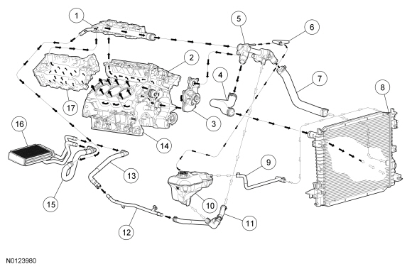
Coolant Flow Diagram
NOTE: Black arrows indicate hot, white arrows indicate cold.
| Item | Part Number | Description |
|---|---|---|
| 1 | 9J447 | Intake manifold |
| 2 | 8050 | LH cylinder head |
| 3 | 8501 | Coolant pump |
| 4 | 8B274 | Upper radiator hose |
| 5 | 8A586 | Thermostat housing |
| 6 | 8075A | Thermostat housing-to-degas bottle hose |
| 7 | 8B273 | Lower radiator hose |
| 8 | 8005 | Radiator |
| 9 | 8075B | Radiator-to-degas bottle hose |
| 10 | 8A080 | Degas bottle |
| 11 | 8K289 | Coolant return hose |
| 12 | 18B402 | Heater outlet tube |
| 13 | 18472B | Heater outlet hose |
| 14 | 6010 | Cylinder block |
| 15 | 18K579 | Heater inlet hose |
| 16 | 18B539 | Heater core |
| 17 | 6049 | RH cylinder head |
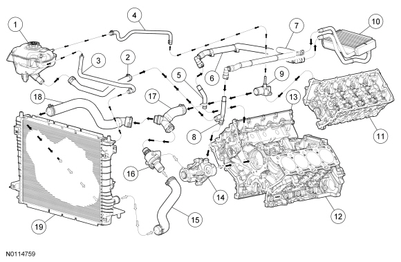
NOTE: Black arrows indicate hot, white arrows indicate cold.
| Item | Part Number | Description |
|---|---|---|
| 1 | 8A080 | Degas bottle |
| 2 | 8K276 | Degas bottle-to-engine hose |
| 3 | 8276 | Radiator-to-degas bottle hose |
| 4 | 8276 | Coolant outlet connector-to-degas bottle hose |
| 5 | 18696 | Heater inlet tube |
| 6 | 18K579 | Heater inlet hose |
| 7 | 18K580 | Heater outlet hose |
| 8 | 18663 | Heater outlet tube |
| 9 | 8594 | Coolant outlet connector |
| 10 | 18B539 | Heater core |
| 11 | 6050 | LH cylinder head |
| 12 | 6010 | Cylinder block |
| 13 | 6049 | RH cylinder head |
| 14 | 8501 | Coolant pump |
| 15 | 8B273 | Lower radiator hose |
| 16 | 8A586 | Thermostat housing |
| 17 | 8566 | Coolant bypass T assembly |
| 18 | 8B274 | Upper radiator hose |
| 19 | 8005 | Radiator |
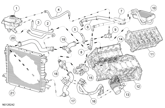
NOTE: Black arrows indicate hot, white arrows indicate cold.
| Item | Part Number | Description |
|---|---|---|
| 1 | 8A080 | Degas bottle |
| 2 | 8K276 | Degas bottle-to-engine hose |
| 3 | 8276 | Radiator-to-degas bottle hose |
| 4 | 8276 | Coolant outlet connector-to-degas bottle hose |
| 5 | 18696 | Heater inlet tube |
| 6 | 18K579 | Heater inlet hose |
| 7 | 18K580 | Heater outlet hose |
| 8 | 18663 | Heater outlet tube |
| 9 | 8594 | Coolant outlet connector |
| 10 | 18B539 | Heater core |
| 11 | 6050 | LH cylinder head |
| 12 | 6010 | Cylinder block |
| 13 | 6A642 | Engine oil cooler |
| 14 | 6049 | RH cylinder head |
| 15 | 8501 | Coolant pump |
| 16 | 6N866 | Lower radiator hose-to-oil cooler hose assembly |
| 17 | 8B273 | Lower radiator hose |
| 18 | 8A586 | Thermostat housing |
| 19 | 8566 | Coolant bypass T assembly |
| 20 | 8B274 | Upper radiator hose |
| 21 | 8005 | Radiator |
NOTE: At 38°C (100°F) ambient temperature, green arrows indicate coolant temperature below 90°C (194°F), amber arrows indicate coolant temperature approximately 90°C (194°F), red arrows indicate coolant temperature above 90°C (194°F),
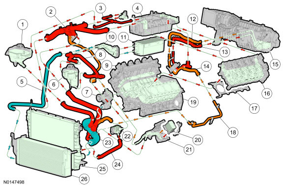
| Item | Part Number | Description |
|---|---|---|
| 1 | 8A080 | Engine cooling system degas bottle |
| 2 | 8A586 | Thermostat housing and hose assembly |
| 3 | 8276 | Upper intake manifold-to-engine system degas bottle hose |
| 4 | 9424 | Upper intake manifold |
| 5 | 8D030 | Supercharger cooling radiator-to-supercharger cooler hose |
| 6 | 8D028 | Supercharger cooling degas bottle |
| 7 | 8501 | Engine cooling system coolant pump |
| 8 | 8D029 | Supercharger cooling degas bottle-to-supercharger coolant pump hose |
| 9 | 6049 | RH cylinder head |
| 10 | 9N491 | Supercharger tube assembly |
| 11 | 6K775 | Supercharger cooler |
| 12 | 18K580 | Heater core outlet hose |
| 13 | 18K579 | Heater core inlet hose |
| 14 | 18C553 | Heater core hose and tube assembly |
| 15 | 19B555 | Heater core and evaporator housing |
| 16 | 8050 | LH cylinder head |
| 17 | 6083 | LH cylinder head gasket |
| 18 | 18663 | Heater outlet tube |
| 19 | 6010 | Engine block |
| 20 | 6L635 | Oil temperature control thermostat |
| 21 | 6881 | Oil filter adapter |
| 22 | 6A642 | Oil Cooler |
| 23 | 8K232 | Supercharger cooling system coolant pump |
| 24 | 8B273 | Lower radiator hose assembly |
| 25 | 8K236 | Supercharger cooling system coolant pump-to-radiator hose |
| 26 | 8005 | Engine cooling system radiator |
| 27 | 8009 | Supercharging cooling system radiator |
NOTE: At 38°C (100°F) ambient temperature, green arrows indicate coolant temperature below 90°C (194°F), amber arrows indicate coolant temperature approximately 90°C (194°F), red arrows indicate coolant temperature above 90°C (194°F),
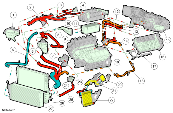
| Item | Part Number | Description |
|---|---|---|
| 1 | 8A080 | Engine cooling system degas bottle |
| 2 | 8A586 | Thermostat housing and hose assembly |
| 3 | 8276 | Upper intake manifold-to-engine system degas bottle hose |
| 4 | 9424 | Upper intake manifold |
| 5 | 8D030 | Supercharger cooling radiator-to-supercharger cooler hose |
| 6 | 8D028 | Supercharger cooling degas bottle |
| 7 | 8501 | Engine cooling system coolant pump |
| 8 | 8D029 | Supercharger cooling degas bottle-to-supercharger coolant pump hose |
| 9 | 6049 | RH cylinder head |
| 10 | 9N491 | Supercharger tube assembly |
| 11 | 6K775 | Supercharger cooler |
| 12 | 18K580 | Heater core outlet hose |
| 13 | 18K579 | Heater core inlet hose |
| 14 | 18C553 | Heater core hose and tube assembly |
| 15 | 19B555 | Heater core and evaporator housing |
| 16 | 8050 | LH cylinder head |
| 17 | 6083 | LH cylinder head gasket |
| 18 | 18663 | Heater outlet tube |
| 19 | 6010 | Engine block |
| 20 | 6A642 | Engine oil cooler |
| 21 | 6881 | Oil filter adapter |
| 22 | 8K232 | Supercharger cooling system coolant pump |
| 23 | 8B273 | Lower radiator hose assembly |
| 24 | 8K236 | Supercharger cooling system coolant pump-to-radiator hose |
| 25 | 8005 | Engine cooling system radiator |
| 26 | 8009 | Supercharging cooling system radiator |