SECTION 303-04B: Fuel Charging and Controls — 5.0L (4V)
| 2014 Mustang Workshop Manual
|
REMOVAL AND INSTALLATION
| Procedure revision date: 01/15/2013
|
Fuel Rail
Material
| Item
| Specification
|
|---|
Motorcraft® SAE 5W-20 Premium Synthetic Blend Motor Oil (US); Motorcraft® SAE 5W-20 Super Premium Motor Oil (Canada)
XO-5W20-QSP (US); CXO-5W20-LSP12 (Canada)
| WSS-M2C945-A
|
Removal
 WARNING: Do not smoke, carry lighted tobacco or have an open flame of any type when working on or near any fuel-related component. Highly flammable mixtures are always present and may be ignited. Failure to follow these instructions may result in serious personal injury.
WARNING: Before working on or disconnecting any of the fuel tubes or fuel system components, relieve the fuel system pressure to prevent accidental spraying of fuel. Fuel in the fuel system remains under high pressure, even when the engine is not running. Failure to follow this instruction may result in serious personal injury.
WARNING: Do not carry personal electronic devices such as cell phones, pagers or audio equipment of any type when working on or near any fuel-related component. Highly flammable mixtures are always present and may be ignited. Failure to follow these instructions may result in serious personal injury.
WARNING: Clean all fuel residue from the engine compartment. If not removed, fuel residue may ignite when the engine is returned to operation. Failure to follow this instruction may result in serious personal injury.
WARNING: Always disconnect the battery ground cable at the battery when working on an evaporative emission (EVAP) system or fuel-related component. Highly flammable mixtures are always present and may be ignited. Failure to follow these instructions may result in serious personal injury.
- Release the fuel system pressure, refer to
Section 310-00
.
- Disconnect the battery ground cable, refer to
Section 414-01
.
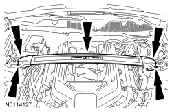
- If equipped, remove the 4 nuts and the strut tower cross brace.
NOTE:
The engine appearance cover rubber grommets may remain on the cover. If so, remove the grommets from the cover and install them on the intake manifold before installing the cover.
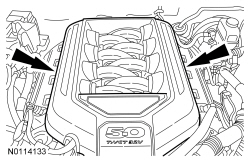
Remove the engine appearance cover.
- Position the heater hoses aside.
- Remove the 2 nuts and the
heater hose support.
- Position the vacuum tube assembly aside.
- Remove the 2 nuts and the
heater hose support.
- Remove the
and
fuel rail insulators.
- Disconnect the 8 fuel injector electrical connectors.
- Disconnect the fuel supply tube, refer to the quick connect procedure in
Section 310-00
.
- Remove the 4 fuel rail bolts.
- Remove the fuel rail and fuel injectors as an assembly from the intake manifold.
- Remove the retaining clips and fuel injectors from the fuel rail.
NOTICE:
Do not reuse the O-ring seals. Failure to follow this direction may cause the fuel system to leak.
Remove and discard the fuel injector O-ring seals.
Installation
NOTICE:
Use O-ring seals that are made of special fuel-resistant material. Use of ordinary O-ring seals may cause the fuel system to leak.
NOTE:
Lubricate the upper and lower fuel injector O-ring seals with clean engine oil prior to installation.
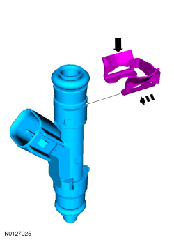
Install new O-ring seals on the fuel injectors.
NOTE:
The fuel injector clip can be reused if it is not damaged during removal. If the clip is reused, the 2 sides of the clip should be squeezed back into shape by placing it between index finger and thumb.
Slide the injector clip into the slot on the injector just below the upper O-ring from the direction opposite the electrical connector. The flanges on the clip should be facing upward.
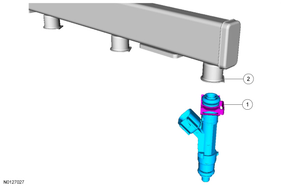
- Install the injector and clip assemblies into the fuel rail with the flat part of the injector clip (1) aligned with the flat part of the fuel rail cup (2) to ensure proper orientation.
- Install the fuel rail and fuel injectors as an assembly onto the intake manifold.
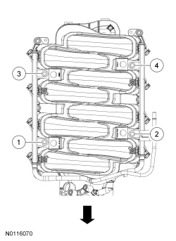
- Install the 4 bolts and tighten in the sequence shown in 3 stages.
- Stage 2: Tighten to 10 Nm (89 lb-in).
- Stage 3: Tighten an additional 90 degrees.
- Connect the fuel supply tube, refer to the quick connect procedure in
Section 310-00
.
- Connect the 8 fuel injector electrical connectors.
- Install the
and
fuel rail insulators.
- Install the
heater hose support and the 2 nuts.
- Tighten to 7 Nm (62 lb-in)
- Install the vacuum tube assembly, the
heater hose support and the 2 nuts.
- Tighten to 7 Nm (62 lb-in)
- Position the heater hoses.
NOTE:
The engine appearance cover rubber grommets may remain on the cover. If so, remove the grommets from the cover and install them on the intake manifold before installing the cover.
Install the engine appearance cover.
- If equipped, install the strut tower cross brace and the 4 nuts.
- Tighten to 35 Nm (26 lb-ft).
- Connect the battery ground cable, refer to
Section 414-01
.