SECTION 303-04C: Fuel Charging and Controls — 5.8L (4V)
| 2014 Mustang Workshop Manual
|
REMOVAL AND INSTALLATION
| Procedure revision date: 01/07/2013
|
Fuel Rail
Material
| Item
| Specification
|
|---|
Motorcraft® SAE 5W-50 Full Synthetic Motor Oil
XO-5W50-QGT
| WSS-M2C931-B
|
Removal and Installation
 WARNING: Do not smoke, carry lighted tobacco or have an open flame of any type when working on or near any fuel-related component. Highly flammable mixtures are always present and may be ignited. Failure to follow these instructions may result in serious personal injury.
WARNING: Do not carry personal electronic devices such as cell phones, pagers or audio equipment of any type when working on or near any fuel-related component. Highly flammable mixtures are always present and may be ignited. Failure to follow these instructions may result in serious personal injury.
WARNING: Before working on or disconnecting any of the fuel tubes or fuel system components, relieve the fuel system pressure to prevent accidental spraying of fuel. Fuel in the fuel system remains under high pressure, even when the engine is not running. Failure to follow this instruction may result in serious personal injury.
WARNING: Clean all fuel residue from the engine compartment. If not removed, fuel residue may ignite when the engine is returned to operation. Failure to follow this instruction may result in serious personal injury.
WARNING: Always disconnect the battery ground cable at the battery when working on an evaporative emission (EVAP) system or fuel-related component. Highly flammable mixtures are always present and may be ignited. Failure to follow these instructions may result in serious personal injury.
- Release the fuel system pressure, refer to
Section 310-00
.
- Disconnect the battery ground cable, refer to
Section 414-01
.
- Remove the Air Cleaner (ACL) outlet pipe, refer to
Section 303-12
.
- Disconnect the Evaporative Emission (EVAP) tube and electrical connector from the
canister purge valve and the brake booster vacuum supply tube from the Throttle Body (TB) spacer. Refer to
Section 310-00
.
- Disconnect the Throttle Position (TP) sensor electrical connector.
- Remove the 4 bolts and the
spacer assembly.
- Tighten to 10 Nm (89 lb-in).
- Disconnect the Intake Air Temperature 2 (IAT2) sensor electrical connector.
- Disconnect the fuel supply tube-to-fuel rail quick connect coupling, refer to
Section 310-00
.
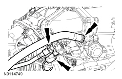
- Disconnect the PCV valve-to-Supercharger (SC) tube quick connect coupling and position aside. For additional information, refer to
Section 310-00
.
- Disconnect the fuel rail pressure and temperature sensor electrical and vacuum connectors.
- Disconnect the 8 fuel injector electrical connectors.
- Remove the 4 fuel rail bolts.
- To install, tighten to 10 Nm (89 lb-in).
- Remove the fuel rail and the 8 fuel injectors.
- Remove the fuel injector clips and the fuel injectors.
- Discard the fuel injector clips.
- Inspect the fuel injector O-ring seals for damage.
- To install, reverse the removal procedure.
- Lubricate the upper and lower fuel injector O-ring seals with clean engine oil prior to installation.
- Install new fuel injector clips.
- Install a new
spacer-to-
gasket.