SECTION 303-04C: Fuel Charging and Controls — 5.8L (4V)
| 2014 Mustang Workshop Manual
|
REMOVAL AND INSTALLATION
| Procedure revision date: 01/07/2013
|
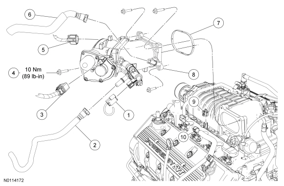
| Item | Part Number | Description |
|---|---|---|
| 1 | Part of 12C508 | Evaporative Emission (EVAP) canister purge valve electrical connector |
| 2 | 9G271 | EVAP canister purge valve vapor tube-to-Throttle Body (TB) spacer quick connect coupling |
| 3 | Part of 12C508 | ETC electrical connector |
| 4 | N806154 | TB spacer bolt (4 required) |
| 5 | Part of 12C508 | Throttle Position (TP) sensor electrical connector |
| 6 | 9C482 | Brake booster-to- TB spacer quick connect coupling |
| 7 | 9L437 | TB spacer-to-Supercharger (SC) gasket |
| 8 | 9E822 | TB spacer assembly |
| 9 | Part of 12C508 | Intake Air Temperature 2 (IAT2) sensor electrical connector |
| 10 | 9J280 | Fuel supply tube-to-fuel rail quick connect coupling |
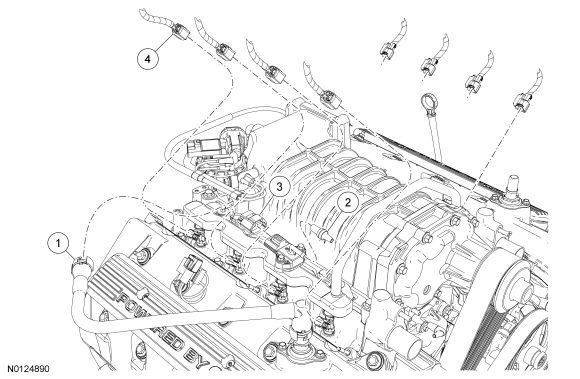
| Item | Part Number | Description |
|---|---|---|
| 1 | 6A664 | PCV valve-to-Supercharger (SC) tube quick connect coupling |
| 2 | 9E498 | FRP and FRT sensor vacuum hose |
| 3 | Part of 12C508 | FRP and FRT sensor electrical connector |
| 4 | Part of 12C508 | Fuel injector electrical connector (8 required) |
| Item | Part Number | Description |
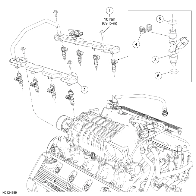
|---|---|---|
| 1 | N804394 | Fuel rail bolt (4 required) |
| 2 | 9F792 | Fuel rail |
| 3 | 9F593 | Fuel injector (8 required) |
| 4 | 9C995 | Fuel injector clip (8 required) |
| 5 | 9229 (part of 9F593) | Upper fuel injector O-ring seal (8 required) |
| 6 | 9229 (part of 9F593) | Lower fuel injector O-ring seal (8 required) |