
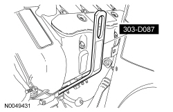
303-D087 (D93P-6001-A1)

303-F070
SECTION 204-01: Front Suspension
| 2014 Mustang Workshop Manual
|
REMOVAL AND INSTALLATION
| Procedure revision date: 08/23/2013
|
| Lifting Bracket, Engine
303-D087 (D93P-6001-A1) |
| Support Bar, Engine
303-F070 |
| Item | Part Number | Description |
|---|---|---|
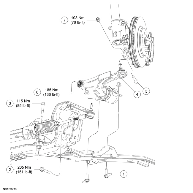
| 1 | W710141 | Lower arm rearward flag bolt (2 required) |
| 2 | W709865 | Lower arm forward bolt |
| 3 | W710909 | Steering gear bolt (2 required) |
| 4 | 3079 LH/ 3078 RH | Lower arm |
| 5 | W711123 | Lower ball joint bolt |
| 6 | W520215 | Lower arm rearward nut (2 required) |
| 7 | W520214 | Lower ball joint nut |
Removal
NOTICE: Suspension fasteners are critical parts that affect the performance of vital components and systems. Failure of these fasteners may result in major service expense. Use the same or equivalent parts if replacement is necessary. Do not use a replacement part of lesser quality or substitute design. Tighten fasteners as specified.
All vehicles
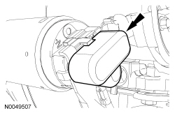
NOTICE: Disconnect the Electronic Power Assist Steering (EPAS) steering gear power supply electrical connector or damage to the steering gear internal power relay may occur resulting in steering gear replacement.
NOTICE: The ignition must be off when disconnecting Electronic Power Assist Steering (EPAS) electrical connectors. Failure to follow this direction may lead to DTCs being set in the EPAS module that can not be cleared, and result in the need to install a new EPAS assembly.
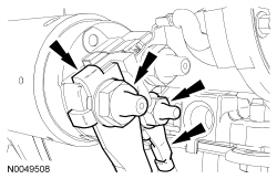
Release the red Connector Position Assurance (CPA) feature and disconnect the Electronic Power Assist Steering (EPAS) power supply electrical connector.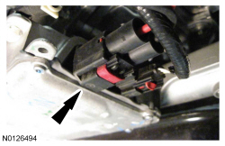
Vehicles with 5.8L (4V) engine
NOTICE: Lift engine approximately 45 mm (1.771 in) from the bottom of the engine mount to the bottom of the engine bracket ensuring that no contact is made with the bulk head or damage to components may occur.
Install the Engine Support Bar.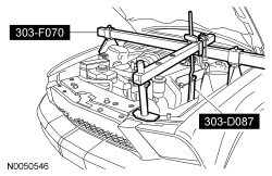
All vehicles
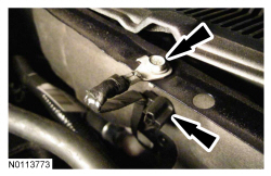
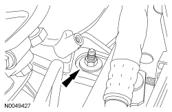
NOTICE: Note the orientation of the lower arm forward bolt and nut. They must be installed using the same orientation or damage to the steering gear bellows boot may occur.
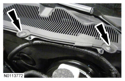
NOTICE: Use care not to damage the steering gear bellows boot while removing the lower arm forward bolt.
Remove and discard the lower arm forward bolt.Installation
All vehicles
NOTE: To ease installation, the position of the lower control arm nut and flag bolt may be reversed to allow installation of the nut from underneath the vehicle.
Install the lower arm and bracket assembly and the lower arm rearward nuts and flag bolts.NOTICE: Use care not to damage the steering gear bellows boot while installing the lower arm forward bolt.
NOTE: Do not tighten the lower arm forward bolt at this time.
Loosely install the lower arm forward bolt.Vehicles with 5.8L (4V) engine
NOTE: While lowering the engine, make sure that the engine bracket aligns to the engine mount stud bolt. If necessary, shift the engine slightly when lowering.
Using the Engine Lifting Bracket and Engine Support Bar, lower the LH side of the engine onto the engine mount.All vehicles
NOTICE: The lower ball joint seal must be fully seated against the wheel spindle or damage to the ball joint may occur.
Position the lower ball joint into the wheel spindle and install the new lower ball joint nut and bolt.NOTE: Make sure the Electronic Power Assist Steering (EPAS) electrical connector is fully seated and the Connector Position Assurance (CPA) feature is engaged.
Connect the Electronic Power Assist Steering (EPAS) power supply electrical connector and secure the red CPA feature.