 WARNING: Do not apply heat or flame to the shock absorber or strut tube. The shock absorber and strut tube are gas pressurized and could explode if heated. Failure to follow this instruction may result in serious personal injury.
SECTION 204-01: Front Suspension
| 2014 Mustang Workshop Manual
|
REMOVAL AND INSTALLATION
| Procedure revision date: 01/07/2013
|
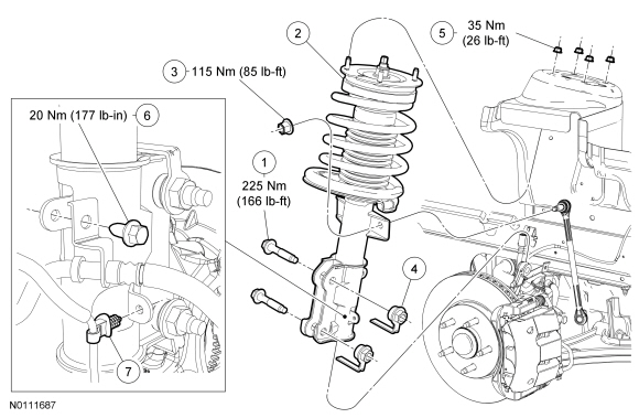
| Item | Part Number | Description |
|---|---|---|
| 1 | W714652 | Strut-to-wheel spindle bolt (2 required) |
| 2 | — | Strut and spring assembly |
| 3 | W712503 | Stabilizer bar link upper nut |
| 4 | W714653 | Strut-to-wheel spindle flagnut (2 required) |
| 5 | W520112 | Strut upper mount nut (4 required) |
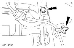
| 6 | N802191 | Brake hose bracket bolt |
| 7 | — | Wheel speed sensor harness retainer (part of 2C204) |
Removal and Installation
WARNING: Do not apply heat or flame to the shock absorber or strut tube. The shock absorber and strut tube are gas pressurized and could explode if heated. Failure to follow this instruction may result in serious personal injury.
WARNING: Keep all body parts clear of shock absorbers or strut rods. Shock absorbers or struts can extend unassisted. Failure to follow this instruction may result in serious personal injury.
NOTICE: Suspension fasteners are critical parts because they affect performance of vital components and systems and their failure may result in major service expense. New parts must be installed with the same part number or equivalent part, if replacement is necessary. Do not use a replacement part of lesser quality or substitute design. Torque values must be used as specified during reassembly to make sure of correct retention of these parts.
NOTICE: Use the hex-holding feature to prevent the studs from turning while removing or installing the stabilizer bar link nuts. The boot seal must not be allowed to twist at all while tightening the nuts or damage to the boot seal may occur.
Remove and discard the stabilizer bar link upper nut and disconnect the link from the strut.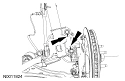
WARNING: Do not apply heat or flame to the shock absorber or strut tube. The shock absorber and strut tube are gas pressurized and could explode if heated. Failure to follow this instruction may result in serious personal injury.
WARNING: Keep all body parts clear of shock absorbers or strut rods. Shock absorbers or struts can extend unassisted. Failure to follow this instruction may result in serious personal injury.
NOTE: If equipped, do not discard the strut-to-spindle cam nuts and bolts.
Remove and discard the strut-to-spindle bolts and flagnuts.NOTICE: Damage to the lower control arm bushings may occur if the lower control arm is not supported.
Carefully lower the lower control arm and remove the strut and spring assembly.