SECTION 204-02: Rear Suspension
| 2014 Mustang Workshop Manual
|
REMOVAL AND INSTALLATION
| Procedure revision date: 01/07/2013
|
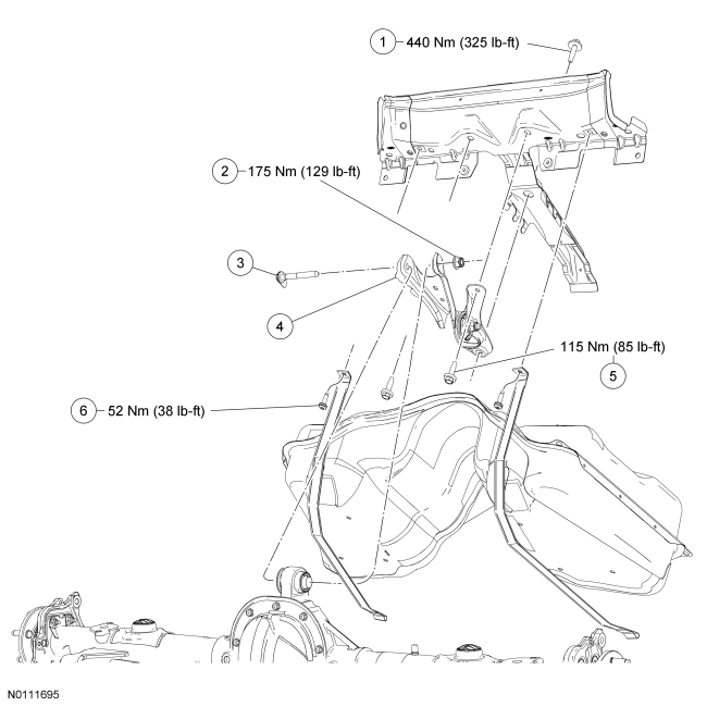
| Item | Part Number | Description |
|---|---|---|
| 1 | W714389 | Upper arm bracket forward bolt |
| 2 | W520215 | Upper arm-to-upper arm bushing nut |
| 3 | W710443 | Upper arm-to-upper arm bushing bolt |
| 4 | 5K671 | Upper arm assembly |
| 5 | W711075 | Upper arm bracket rearward bolt (2 required) |
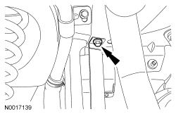
| 6 | W710947 | Fuel tank strap bolt (2 required) |
Removal and Installation
NOTICE: Suspension fasteners are critical parts because they affect performance of vital components and systems and their failure may result in major service expense. New parts must be installed with the same part numbers or equivalent part, if replacement is necessary. Do not use a replacement part of lesser quality or substitute design. Torque values must be used as specified during reassembly to make sure of correct retention of these parts.
NOTICE: The upper arm is a 2-piece design and is replaced as an assembly. Do not remove or loosen the nut and bolt that joins the 2 pieces together. The assembly is set at ride height during production, loosening the nut and bolt will disturb this setting.
NOTICE: Tighten the upper arm fasteners while the suspension is at curb height or bushing damage and incorrect clamp load may occur.
To install, reverse the removal procedure.