
204-354
SECTION 204-04: Wheels and Tires
| 2014 Mustang Workshop Manual
|
DISASSEMBLY AND ASSEMBLY
| Procedure revision date: 01/07/2013
|
| Digital Tire Pressure Gauge
204-354 |
Disassembly
 WARNING: The tire pressure monitoring system (TPMS) sensor battery may release hazardous chemicals if exposed to extreme mechanical damage. If these chemicals contact the skin or eyes, flush immediately with water for a minimum of 15 minutes and get prompt medical attention. If any part of the battery is swallowed, contact a physician immediately. When disposing of TPMS sensors, follow the correct procedures for hazardous material disposal. Failure to follow these instructions may result in serious personal injury.
NOTICE: Failure to follow the instructions below may result in damage to the Tire Pressure Monitoring System (TPMS) sensor.
NOTICE: The TPMS sensor is mounted to the valve stem. Removal of the valve stem requires dismounting the tire from the wheel and removal of the TPMS sensor.
NOTE: Use only the Digital Tire Pressure Gauge any time tire pressures are measured to be sure that accurate values are obtained.
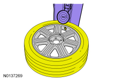
NOTICE: Do not allow the tire beads to move beyond the wheel mid-plane (middle of the wheel) when separating the beads from the wheels, damage to the TPMS sensor may occur.
NOTICE: Tire and valve stem position is critical to prevent damage to the TPMS sensor when using a paddle-type bead separator.
NOTE: Some machines may have a nylon roller bead separator at the 12 o'clock position instead of the paddle-type bead separator at the 3 o'clock position.
Position the wheel and tire assembly on a suitable tire machine and separate both beads of the tire from the wheel.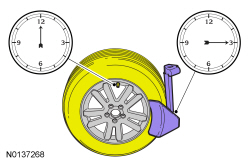
NOTE: Index-mark the valve stem and wheel weight positions on the tire.
Place the wheel and tire assembly on the turntable of the tire machine with the valve stem at the 11:30 position and the machine arm at the 12 o'clock position and dismount the outer bead from the wheel.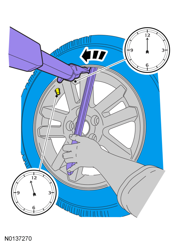
NOTE: A new valve stem must be installed whenever a new tire or wheel is installed.
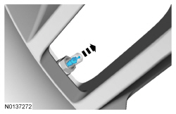
Remove the TPMS sensor in the following sequence.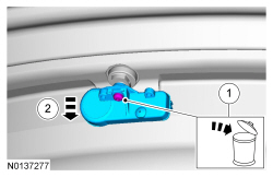

Assembly
NOTE: Ensure that the bushing and the washer are properly installed or air leaks will occur.
Install the valve stem in the following sequence.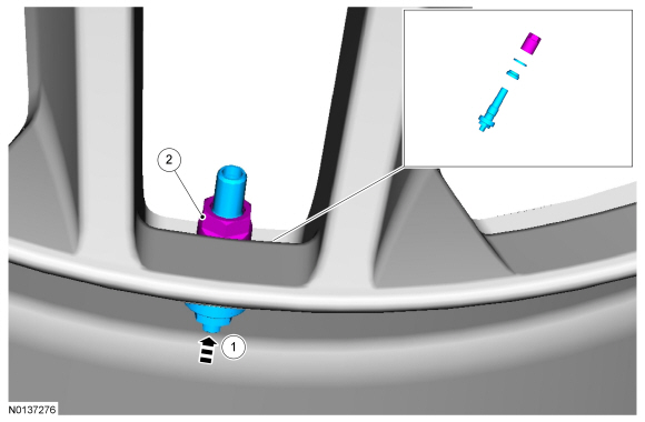
NOTE: When installing a new wheel, always install a new valve stem and sensor screw. Reuse the TPMS sensor from the previous wheel if possible. The TPMS will not have to be trained if the sensor is reused.
NOTE: If the TPMS sensor is being reused, inspect the TPMS sensor for damage and install a new sensor as necessary.
Install the TPMS sensor in the following sequence.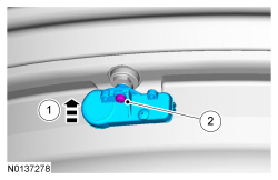
NOTE: Lubricate the tire beads using a suitable fast-drying, corrosion-inhibiting tire bead lubricant.
NOTE: Do not mount the tire at this time.
Position the wheel on the turntable of the tire machine, then lubricate and position the bottom bead of the tire on the wheel.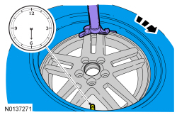
NOTE: Use only the Digital Tire Pressure Gauge any time tire pressures are measured to make sure that accurate values are obtained.
Install the valve stem core and inflate the tire to the pressure specified on the Vehicle Certification (VC) label located on the driver door or door pillar.
WARNING: If there is a need to exceed the maximum pressure indicated on the sidewall of the tire in order to seat the beads, follow all steps listed below. Failure to follow these steps may result in serious personal injury.