
164-R2402 or equivalent
SECTION 205-00: Driveline System — General Information
| 2014 Mustang Workshop Manual
|
GENERAL PROCEDURES
| Procedure revision date: 01/07/2013
|
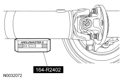
| Anglemaster II Driveline Inclinometer/Protractor
164-R2402 or equivalent |
NOTE: This procedure does not apply to CV joints, flex couplers or double cardan joints that are used in some driveshafts. This check is for single-cross and roller-style joints found in the driveshafts.
NOTE: Prior to checking driveline angularity, inspect the U-joints for correct operation.
NOTE: An incorrect driveline angle can cause a vibration or shudder. For additional information, refer to Section 100-04 .
NOTE: Driveline angularity is the angular relationship between the engine crankshaft, the driveshaft and the rear axle pinion. Factors determining driveline angularity include ride height, rear spring and engine mounts.
All vehicles
Vehicles with flat-flanged, split-pin or slip-flanged U-joints
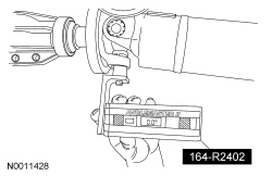
NOTE: If equipped, remove the snap ring to allow access to the base of the U-joint cup. Make sure the Anglemaster II Driveline Inclinometer/Protractor is seated against the U-joint cup.
NOTE: Rotate the driveshaft until the flange U-joint cup is parallel with the floor. This will simplify taking measurements.
To check the U-joint operating angle, install the Anglemaster II Driveline Inclinometer/Protractor. Check and record the flange angle as angle A.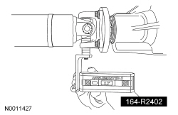
Multiple piece driveshafts
NOTE: Repeat this step for each center support bearing on the driveshaft.
NOTE: It is not necessary to remove the U-joint snap ring, if equipped, for these measurements.
Using the Anglemaster II Driveline Inclinometer/Protractor, measure the slope of the components in front and behind the center support bearing U-joint in the area indicated. Record the front component as angle A and the rear component as angle B.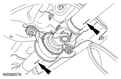
All vehicles
NOTE: When 2 connected components slope in the same direction, subtract the smallest number from the larger number to find the U-joint operating angle. When 2 connected components slope in the opposite direction, add the measurements to find the U-joint operating angle.
Calculate the difference in the slope of the components to determine the U-joint operating angle.