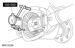
100-002 (TOOL-4201-C)

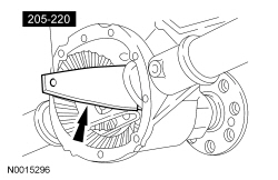
205-220 (T85L-4067-AH)
SECTION 205-02: Rear Drive Axle/Differential — Ford 8.8-Inch Ring Gear
| 2014 Mustang Workshop Manual
|
GENERAL PROCEDURES
| Procedure revision date: 01/07/2013
|
| Dial Indicator Gauge With Holding Fixture
100-002 (TOOL-4201-C) |
| Installer, Differential Shim
205-220 (T85L-4067-AH) |
| Item | Specification |
|---|---|
| Motorcraft® High Contrast Hypoid Gear Marking Compound
XG-14 | — |
NOTE: Index-mark the position of the differential bearing caps, as arrows may not be visible. The differential bearing caps must be installed in their original locations and positions.
Remove the 4 differential bearing cap bolts and 2 caps.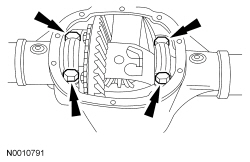
| Backlash Change Required | Thickness Change Required | ||
|---|---|---|---|
| mm | Inch | mm | Inch |
| 0.025 | 0.001 | 0.050 | 0.002 |
| 0.050 | 0.002 | 0.050 | 0.002 |
| 0.076 | 0.003 | 0.101 | 0.004 |
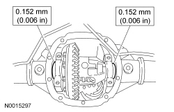
| 0.101 | 0.004 | 0.152 | 0.006 |
| 0.127 | 0.005 | 0.152 | 0.006 |
| 0.152 | 0.006 | 0.203 | 0.008 |
| 0.177 | 0.007 | 0.254 | 0.010 |
| 0.203 | 0.008 | 0.254 | 0.010 |
| 0.228 | 0.009 | 0.304 | 0.012 |
| 0.254 | 0.010 | 0.355 | 0.014 |
| 0.279 | 0.011 | 0.355 | 0.014 |
| 0.304 | 0.012 | 0.406 | 0.016 |
| 0.330 | 0.013 | 0.457 | 0.018 |
| 0.335 | 0.014 | 0.457 | 0.018 |
| 0.381 | 0.015 | 0.508 | 0.020 |
Differential Shim Size Chart 4067
| Stripes and Color Code | Dimension A | |
|---|---|---|
| mm | Inch | |
| 2 — C-COAL | 7.7978-7.8105 | 0.3070-0.3075 |
| 1 — C-COAL | 7.7470-7.7597 | 0.3050-0.3055 |
| 5 — BLU | 7.6962-7.7089 | 0.3030-0.3035 |
| 4 — BLU | 7.6454-7.6581 | 0.3010-0.3015 |
| 3 — BLU | 7.5946-7.6073 | 0.2990-0.2995 |
| 2 — BLU | 7.5458-7.5565 | 0.2970-0.2975 |
| 5 — PINK | 7.4422-7.4549 | 0.2930-0.2935 |
| 4 — PINK | 7.3914-7.4041 | 0.2910-0.2915 |
| 3 — PINK | 7.3406-7.3533 | 0.2890-0.2895 |
| 2 — PINK | 7.2898-7.3025 | 0.2870-0.2875 |
| 1 — PINK | 7.2390-7.2517 | 0.2850-0.2855 |
| 5 — GRN | 7.1882-7.2009 | 0.2830-0.2835 |
| 4 — GRN | 7.1374-7.1501 | 0.2810-0.2815 |
| 3 — GRN | 7.0866-7.0993 | 0.2790-0.2795 |
| 2 — GRN | 7.0358-7.0485 | 0.2770-0.2775 |
| 1 — GRN | 6.9850-7.0485 | 0.2750-0.2755 |
| 5 — WH | 6.9342-6.9469 | 0.2730-0.2735 |
| 4 — WH | 6.8834-6.8961 | 0.2710-0.2715 |
| 3 — WH | 6.8326-6.8453 | 0.2690-0.2695 |
| 2 — WH | 6.7818-6.7945 | 0.2670-0.2675 |
| 1 — WH | 6.7310-6.7437 | 0.2650-0.2655 |
| 5 — YEL | 6.6802-6.6929 | 0.2630-0.2635 |
| 4 — YEL | 6.6294-6.6421 | 0.2610-0.2615 |
| 3 — YEL | 6.5786-6.5913 | 0.2590-0.2595 |
| 2 — YEL | 6.5278-6.5405 | 0.2570-0.2575 |
| 1 — YEL | 6.4770-6.4897 | 0.2550-0.2555 |
| 5 — ORNG | 6.4262-6.4389 | 0.2530-0.2535 |
| 4 — ORNG | 6.3754-6.3881 | 0.2510-0.2515 |
| 3 — ORNG | 6.3246-6.3373 | 0.2490-0.2495 |
| 2 — ORNG | 6.2738-6.2865 | 0.2470-0.2475 |
| 1 — ORNG | 6.2223-6.2357 | 0.2450-0.2455 |
| 2 — RED | 6.1722-6.1849 | 0.2430-0.2435 |
| 1 — RED | 6.1214-6.1341 | 0.2410-0.2415 |