SECTION 205-02: Rear Drive Axle/Differential — Ford 8.8-Inch Ring Gear
| 2014 Mustang Workshop Manual
|
REMOVAL AND INSTALLATION
| Procedure revision date: 01/07/2013
|
| Item | Specification |
|---|---|
| Additive Friction Modifier
XL-3 (US); CXL-3 (Canada) | EST-M2C118-A |
| Motorcraft® SAE 75W-140 Synthetic Rear Axle Lubricant
XY-75W140-QL (US); CXY-75W140-1L (Canada) | WSL-M2C192-A and GL-5 |
| Motorcraft® SAE 75W-85 Premium Synthetic Hypoid Gear Lubricant
XY-75W85-QL | WSS-M2C942-A |
| Item | Part Number | Description |
|---|---|---|
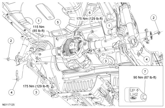
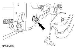
| 1 | — | Shock absorber lower bolts (part of service kit 18008) (2 required) |
| 2 | — | Shock absorber lower flag nuts (part of service kit 18008) (2 required) |
| 3 | W704888 | Lower arm bolts (2 required) |
| 4 | W704991 | Lower arm nuts (2 required) |
| 5 | W710443 | Upper arm bushing bolt |
| 6 | W520215 | Upper arm bushing nut |
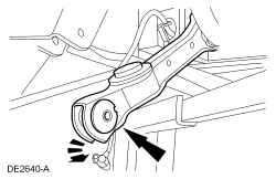
| 7 | 4A263 | Mass dampner (LH shown RH similar) |
Removal
All vehicles
NOTICE: Suspension fasteners are critical parts because they affect performance of vital components and systems and their failure may result in major service expense. New parts must be installed with the same part numbers or equivalent part, if replacement is necessary. Do not use a replacement part of lesser quality or substitute design. Torque values must be used as specified during reassembly to make sure of correct retention of these parts.
Convertibles
All vehicles

NOTE: Secure the differential housing to the transmission jack with a suitable strap.
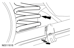
Support the differential housing with a suitable transmission jack.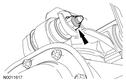
Installation
All vehicles
NOTICE: Tighten the new suspension fasteners while the suspension is at curb height or bushing damage and incorrect clamp load may occur.
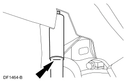
Using 2 jackstands, raise the rear axle so the mark made on the rear shock absorber during removal lines up with the protective sleeve.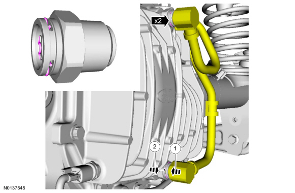
Convertibles
All vehicles
NOTE: Service refill capacities are determined by filling the axle to a level of 5mm below the bottom of the fill hole with the axle at ride height.
If equipped with a differential oil cooler, Remove the axle plug and fill the axle with 1.89-2.01L (4-4.25 pt) of axle lubricant and a additional 4.0 oz of friction modifier additive, then use a scan tool to operate the oil cooler pump and add a additional 1.10L (2 pt) of axle lubricant and a additional 2 oz of friction modifier and install the filler plug.