205-D072 (D97L-4221-A) or equivalent

205-022 (T66L-4204-A)

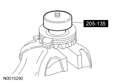
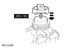
205-135 (T80P-4946-A)

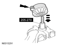
205-270 (T87T-4946-A)

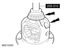
205-010 (T57L-4221-A2)

205-D016 (D80L-630-5) or equivalent
SECTION 205-02: Rear Drive Axle/Differential — Ford 8.8-Inch Ring Gear
| 2014 Mustang Workshop Manual
|
DISASSEMBLY AND ASSEMBLY
| Procedure revision date: 01/07/2013
|
| 2 Jaw Puller
205-D072 (D97L-4221-A) or equivalent |
| Gauge, Differential Clutch
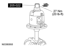
205-022 (T66L-4204-A) |
| Gauge, Differential Clutch
205-135 (T80P-4946-A) |
| Gauge, Differential Clutch
205-270 (T87T-4946-A) |
| Installer, Differential Side Bearing
205-010 (T57L-4221-A2) |
| Step Plate
205-D016 (D80L-630-5) or equivalent |
| Item | Specification |
|---|---|
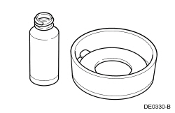
| Additive Friction Modifier
XL-3 (US); CXL-3 (Canada) | EST-M2C118-A |
| Maximum Strength Retaining Compound
Loctite® 638™ | — |
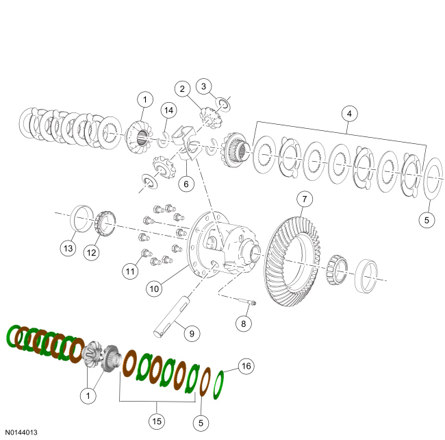
| Item | Part Number | Description |
|---|---|---|
| 1 | 4236 | Differential side gear |
| 2 | 4215 | Differential pinion gear |
| 3 | 4230 | Differential pinion gear thrust washer |
| 4 | 4947 | Differential clutch pack (with differential S-type clutch spring) |
| 5 | 4A324 | Rear axle differential clutch shim |
| 6 | 4214 | Differential S-type clutch spring |
| 7 | 4209 | Differential ring gear |
| 8 | 387426-S101 | Differential pinion shaft lock bolt |
| 9 | 4211 | Differential pinion shaft |
| 10 | 4204 | Differential case |
| 11 | 4216 | Differential ring gear bolt |
| 12 | 4221 | Differential bearing |
| 13 | 4222 | Differential bearing cup |
| 14 | 4N237 | Axle shaft U-washer |
| 15 | 4767 | Differential clutch (without differential S-type clutch spring) |
| 16 | 4214 | Belleville washer (without differential S-type clutch spring) |
Disassembly
All differentials
NOTE: Care should be taken not to damage the differential ring gear bolt hole threads.
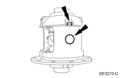
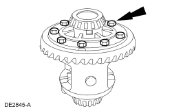
Insert a punch in the differential ring gear bolt holes and drive the differential ring gear off.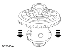
NOTE: The differential flange and ring gear flange must be free of any old retaining compound. Failure to clean the surfaces can result in ring gear runout concerns.
Clean all traces of the old retaining compound from the differential flange and the ring gear flange.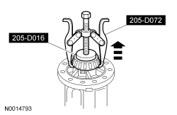

With differential S-type clutch spring
NOTE: Due to the spring tension, care must be used when removing the differential clutch spring.
Remove the differential clutch spring.
NOTE: Keep the differential clutch packs in order. Do not mix the differential clutch packs. The differential clutch packs must be reassembled in the same sequence.
If equipped with a S-type clutch spring, remove the differential clutch packs and differential side gears and tag them RH and LH with the selective shim.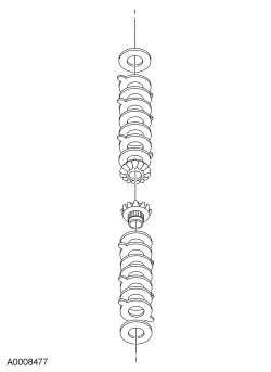
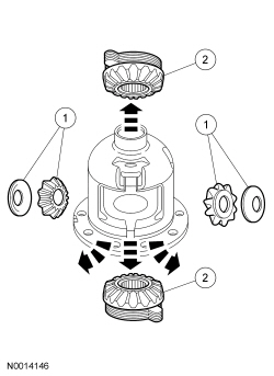
Without differential S-type clutch spring
NOTE: Do not throw away the belleville washers. The bellville washers will be reused.
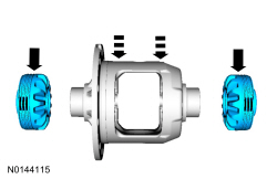
Remove the differential gears.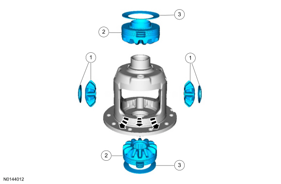
NOTE: Keep the differential clutch packs in order. Do not mix the differential clutch packs. The differential clutch packs must be reassembled in the same sequence.
Remove the differential clutch packs and differential side gears and tag them RH and LH with the selective shim.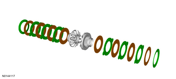
Assembly
All differentials
Without differential S-type clutch spring
NOTE: Do not mix the clutch plates, clutch discs or shim from one side with the other.
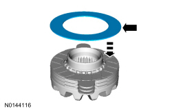
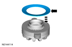
Assemble the differential clutch packs on their respective differential side gear.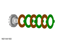
With differential S-type clutch spring
NOTE: Do not mix the clutch plates, clutch discs or shim from one side with the other.
Assemble the differential clutch packs on their respective differential side gear.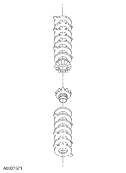
All differentials
NOTE: Selective shims shown are available as part of the clutch pack replacement kit.
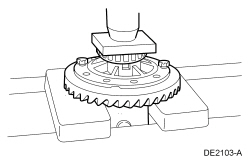
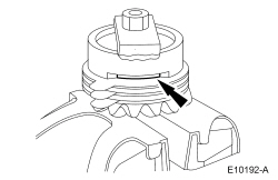
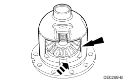
Select and insert the thickest feeler gauge blade that will enter between the tool and the differential clutch pack. Refer to the chart to determine the correct thickness clutch shim to use.Selective Shims
| Feeler Gauge Thickness | Part Number | Description |
| 0.072 - 0.080 | EOAZ-4A324-G | 0.025 inch |
| 0.081 - 0.085 | EOAZ-4A324-H | 0.030 inch |
| 0.086 - 0.090 | EOAZ-4A324-C | 0.035 inch |
| 0.091 - 0.095 | EOAZ-4A324-D | 0.040 inch |
| 0.096 - 0101 | EOAZ-4A324-F | 0.045 inch |
Without differential S-type clutch spring
All differentials
With differential S-type clutch spring
All differentials
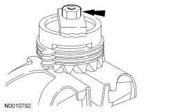
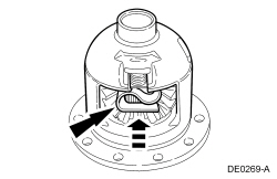
NOTE: The pinion shaft may require to be tapped in with a soft-faced hammer.
Install the differential pinion shaft and install a new bolt finger-tight without tightening into the loctite covered area of the bolt.