
206-026 (T87P-2588-A)

SECTION 206-00: Brake System — General Information
| 2014 Mustang Workshop Manual
|
GENERAL PROCEDURES
| Procedure revision date: 01/07/2013
|
| Adapter for Adjuster, Rear Brake Caliper Piston
206-026 (T87P-2588-A) |
|
Vehicle Communication Module (VCM) and Integrated Diagnostic System (IDS) software with appropriate hardware, or equivalent scan tool
|
| Item | Specification |
|---|---|
| High Performance DOT 3 Motor Vehicle Brake Fluid
PM-1-C (US); CPM-1-C (Canada) | WSS-M6C62-A or WSS-M6C65-A1 |
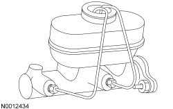
Master Cylinder
 WARNING: Do not use any fluid other than clean brake fluid meeting manufacturer's specification. Additionally, do not use brake fluid that has been previously drained. Following these instructions will help prevent system contamination, brake component damage and the risk of serious personal injury.
WARNING: Carefully read cautionary information on product label. For emergency medical information seek medical advice. In the USA or Canada on Ford/Motorcraft products call: 1-800-959-3673. For additional information, consult the product Material Safety Data Sheet (MSDS) if available. Failure to follow these instructions may result in serious personal injury.
WARNING: Do not allow the brake master cylinder to run dry during the bleeding operation. Master cylinder may be damaged if operated without fluid, resulting in degraded braking performance. Failure to follow this instruction may result in serious personal injury.
NOTICE: Do not spill brake fluid on painted or plastic surfaces or damage to the surface may occur. If brake fluid is spilled onto a painted or plastic surface, immediately wash the surface with water.
NOTE: When a new brake master cylinder has been installed or the system has been emptied, or partially emptied, it should be primed to prevent air from entering the system.
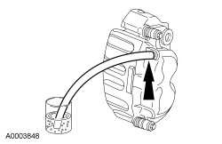
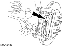
Front Brake Caliper
WARNING: Do not use any fluid other than clean brake fluid meeting manufacturer's specification. Additionally, do not use brake fluid that has been previously drained. Following these instructions will help prevent system contamination, brake component damage and the risk of serious personal injury.
WARNING: Carefully read cautionary information on product label. For emergency medical information seek medical advice. In the USA or Canada on Ford/Motorcraft products call: 1-800-959-3673. For additional information, consult the product Material Safety Data Sheet (MSDS) if available. Failure to follow these instructions may result in serious personal injury.
WARNING: Do not allow the brake master cylinder to run dry during the bleeding operation. Master cylinder may be damaged if operated without fluid, resulting in degraded braking performance. Failure to follow this instruction may result in serious personal injury.
NOTICE: Do not spill brake fluid on painted or plastic surfaces or damage to the surface may occur. If brake fluid is spilled onto a painted or plastic surface, immediately wash the surface with water.
NOTE: When any part of the hydraulic system is disconnected for repair or installation of new components, air can get into the system and cause spongy brake pedal action. This requires bleeding of the hydraulic system after it is correctly connected. The hydraulic system can be bled manually or with pressure bleeding equipment.
NOTE: Due to the complexity of the fluid path within the rear integral parking brake calipers, it is necessary to follow this procedure when new calipers are installed. This procedure is necessary only when installing a new rear brake caliper. To bleed the brake system, refer to Brake System Bleeding in this section.
All vehicles
Vehicles equipped with 2 piston calipers
Vehicles equipped with 4 or 6 piston calipers
All vehicles
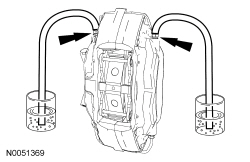
Rear Brake Caliper
WARNING: Do not use any fluid other than clean brake fluid meeting manufacturer's specification. Additionally, do not use brake fluid that has been previously drained. Following these instructions will help prevent system contamination, brake component damage and the risk of serious personal injury.
WARNING: Carefully read cautionary information on product label. For emergency medical information seek medical advice. In the USA or Canada on Ford/Motorcraft products call: 1-800-959-3673. For additional information, consult the product Material Safety Data Sheet (MSDS) if available. Failure to follow these instructions may result in serious personal injury.
WARNING: Do not allow the brake master cylinder to run dry during the bleeding operation. Master cylinder may be damaged if operated without fluid, resulting in degraded braking performance. Failure to follow this instruction may result in serious personal injury.
NOTICE: Do not spill brake fluid on painted or plastic surfaces or damage to the surface may occur. If brake fluid is spilled onto a painted or plastic surface, immediately wash the surface with water.
NOTE: When any part of the hydraulic system is disconnected for repair or installation of new components, air can get into the system and cause spongy brake pedal action. This requires bleeding of the hydraulic system after it is correctly connected. The hydraulic system can be bled manually or with pressure bleeding equipment.
NOTE: Due to the complexity of the fluid path within the rear integral parking brake calipers, it is necessary to follow this procedure when new calipers are installed. This procedure is necessary only when installing a new rear brake caliper. To bleed the brake system, refer to Brake System Bleeding in this section.
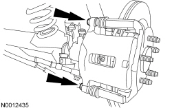
NOTE: Place a shop towel between the caliper and the brake disc.
Install the brake caliper using the 2 brake caliper bolts.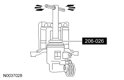
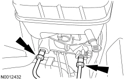
ABS Hydraulic Control Unit (HCU) Bleeding
WARNING: Do not use any fluid other than clean brake fluid meeting manufacturer's specification. Additionally, do not use brake fluid that has been previously drained. Following these instructions will help prevent system contamination, brake component damage and the risk of serious personal injury.
WARNING: Carefully read cautionary information on product label. For emergency medical information seek medical advice. In the USA or Canada on Ford/Motorcraft products call: 1-800-959-3673. For additional information, consult the product Material Safety Data Sheet (MSDS) if available. Failure to follow these instructions may result in serious personal injury.
WARNING: Do not allow the brake master cylinder to run dry during the bleeding operation. Master cylinder may be damaged if operated without fluid, resulting in degraded braking performance. Failure to follow this instruction may result in serious personal injury.
NOTICE: Do not spill brake fluid on painted or plastic surfaces or damage to the surface may occur. If brake fluid is spilled onto a painted or plastic surface, immediately wash the surface with water.
NOTE: This procedure is only required when a new Hydraulic Control Unit (HCU) is installed.
NOTE: When any part of the hydraulic system is disconnected for repair or installation of new components, air can get into the system and cause spongy brake pedal action. This requires bleeding of the hydraulic system after it is correctly connected. The hydraulic system can be bled manually or with pressure bleeding equipment.