SECTION 206-06: Hydraulic Brake Actuation
| 2014 Mustang Workshop Manual
|
REMOVAL AND INSTALLATION
| Procedure revision date: 01/07/2013
|
NOTE: Manual transmission pedal assembly shown, automatic transmission pedal assembly similar.
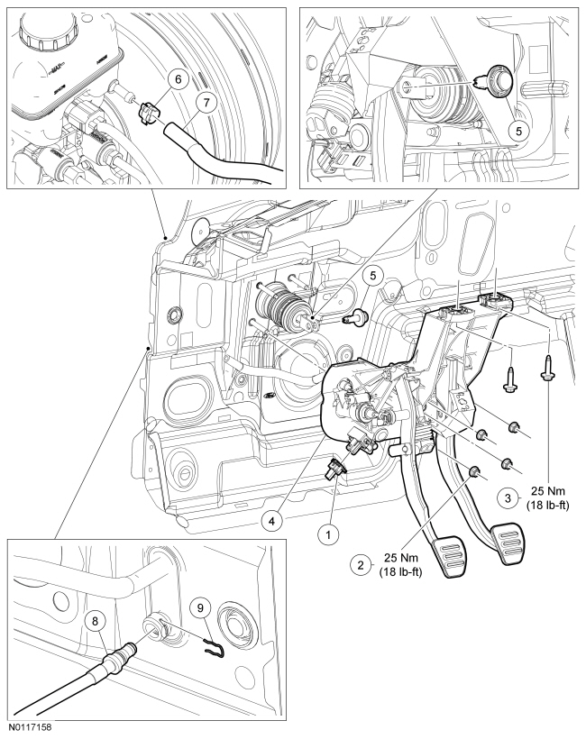
| Item | Part Number | Description |
|---|---|---|
| 1 | — | Clutch Pedal Position (CPP) switch connector (part of 12638) |
| 2 | W520112 | Brake booster nut (4 required) |
| 3 | W707108 | Brake pedal bracket bolt (2 required) |
| 4 | 2455 | Brake pedal and bracket |
| 5 | 2L523 | Brake booster push rod clevis locking pin |
| 6 | — | Spring clamp (part of 7A543) |
| 7 | — | Clutch low-pressure hydraulic hose (part of 7A543) |
| 8 | — | Clutch pedal high-pressure hydraulic hose (part of 7A512) |
| 9 | — | Hairpin clip (part of 7A512) |
Removal and Installation
All vehicles
NOTICE: Do not service the brake pedal without first removing the stoplamp switch. Remove this switch with the brake pedal in the at-rest position. Attempting to remove the switch when the plunger is extended (during pedal apply) results in damage to the switch.
Remove the stoplamp switch. For additional information, refer to Section 417-01 .Manual transmission vehicles
NOTICE: Do not service the brake pedal and bracket assembly without first removing the speed control deactivator switch. Remove this switch with the clutch pedal in the at-rest position. Attempting to remove the switch when the plunger is extended (during pedal apply) results in damage to the switch.
Remove the clutch pedal speed control deactivator switch. For additional information, refer to Section 419-03 .NOTE: The clutch master cylinder is self-bleeding. Pump the clutch pedal until all the air is forced back into the brake master cylinder reservoir.
Remove the hairpin clip and disconnect the clutch pedal high pressure hydraulic hose from the clutch master cylinder.All vehicles
NOTE: The booster push rod clevis locking pin is a one-time use only part. Any time the booster push rod clevis locking pin is removed, replace with a new booster push rod clevis locking pin.
NOTE: Use an 11 mm, 12-point socket or wrench to compress the 2 locking tabs on the clevis pin.
Compress the clevis pin locking tabs and pull outward on the opposite end of the pin, then remove and discard the clevis locking pin.NOTICE: Do not press, pull or otherwise move the brake pedal or clutch pedal while installing the stoplamp switch or speed control deactivator switch. Install these switches with the booster push rod attached to the brake pedal and with the brake pedal and clutch pedal in the at-rest position. Installing these switches with the pedals in any other position results in incorrect adjustment and damages the switches.
To install, reverse the removal procedure.