SECTION 206-09: Anti-Lock Brake System (ABS) and Stability Control
| 2014 Mustang Workshop Manual
|
REMOVAL AND INSTALLATION
| Procedure revision date: 01/07/2013
|
|
Vehicle Communication Module (VCM) and Integrated Diagnostic System (IDS) software with appropriate hardware, or equivalent scan tool
|
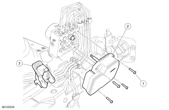
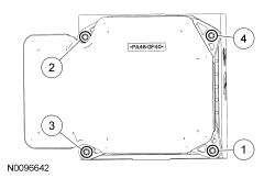
| Item | Part Number | Description |
|---|---|---|
| 1 | — | ABS module screw (4 required) (part of 2C219 and 2C215 service kits) |
| 2 | 2C219 | ABS module |
| 3 | — | ABS module electrical connector (part of 14A005) |
Removal and Installation
NOTICE: Electronic modules are sensitive to electrical charges. The Anti-lock Brake System (ABS) module can be damaged if exposed to these charges.