
SECTION 206-09: Anti-Lock Brake System (ABS) and Stability Control
| 2014 Mustang Workshop Manual
|
REMOVAL AND INSTALLATION
| Procedure revision date: 01/07/2013
|
|
Vehicle Communication Module (VCM) and Integrated Diagnostic System (IDS) software with appropriate hardware, or equivalent scan tool
|
| Item | Specification |
|---|---|
| High Performance DOT 3 Motor Vehicle Brake Fluid
PM-1-C (US); CPM-1-C (Canada) | WSS-M6C62-A or WSS-M6C65-A1 |
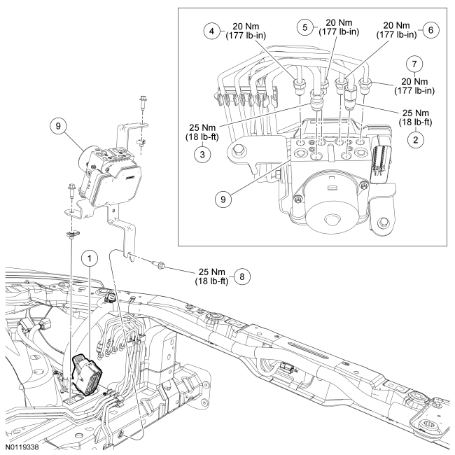
| Item | Part Number | Description |
|---|---|---|
| 1 | — | ABS module electrical connector (part of 14A005) |
| 2 | — | Master cylinder primary brake tube fitting (part of 2269) |
| 3 | — | Master cylinder secondary brake tube fitting (part of 2269) |
| 4 | — | RH front brake tube fitting (part of 2C296B) |
| 5 | — | LH front brake tube fitting (part of 2C296A) |
| 6 | — | RH rear brake tube fitting (part of 2C360) |
| 7 | — | LH rear brake tube fitting (part of 2C360) |
| 8 | W500223 | Hydraulic Control Unit (HCU) bracket-to-frame bolt (3 required) |
| 9 | 2C215 | HCU |
Removal and Installation
 WARNING: Do not use any fluid other than clean brake fluid meeting manufacturer's specification. Additionally, do not use brake fluid that has been previously drained. Following these instructions will help prevent system contamination, brake component damage and the risk of serious personal injury.
WARNING: Carefully read cautionary information on product label. For emergency medical information seek medical advice. In the USA or Canada on Ford/Motorcraft products call: 1-800-959-3673. For additional information, consult the product Material Safety Data Sheet (MSDS) if available. Failure to follow these instructions may result in serious personal injury.
NOTICE: Do not spill brake fluid on painted or plastic surfaces or damage to the surface may occur. If brake fluid is spilled onto a painted or plastic surface, immediately wash the surface with water.
NOTE: The brake tubes must be installed in the same location as removed.
Loosen the 6 brake tube fittings, disconnect and position the brake tubes aside.