SECTION 307-01: Automatic Transaxle/Transmission — 6R80
| 2014 Mustang Workshop Manual
|
DESCRIPTION AND OPERATION
| Procedure revision date: 01/07/2013
|
Pump Assembly and Transmission Fluid Filter
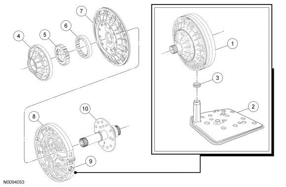
This transmission has a gear type pump that supplies transmission fluid pressure to the hydraulic system.
The inner (drive) gear is turned by the torque converter hub.
The transmission fluid pump has the following parts:
The transmission fluid pump draws transmission fluid from the sump area, formed by the transmission fluid pan, through the transmission fluid filter, which is installed into the intermediate plate portion of the pump assembly and sealed by a rubber seal. A magnet attached to the transmission fluid pan collects any metallic material in the transmission fluid.
| Item | Part Number | Description |
|---|---|---|
| 1 | 7A103 | Transmission fluid pump assembly |
| 2 | 7A098 | Transmission fluid filter |
| 3 | — | Transmission fluid filter seal (part of 7A098) |
| 4 | — | Transmission fluid pump body (part of 7A103) |
| 5 | — | Inner (drive) gear (part of 7A103) |
| 6 | — | Outer (driven) gear (part of 7A103) |
| 7 | — | Centering plate (part of 7A103) |
| 8 | — | Intermediate plate (part of 7A103) |
| 9 | — | Filter suction port |
| 10 | — | Stator shaft (part of 7A103) |
Transmission Fluid Level Indicator
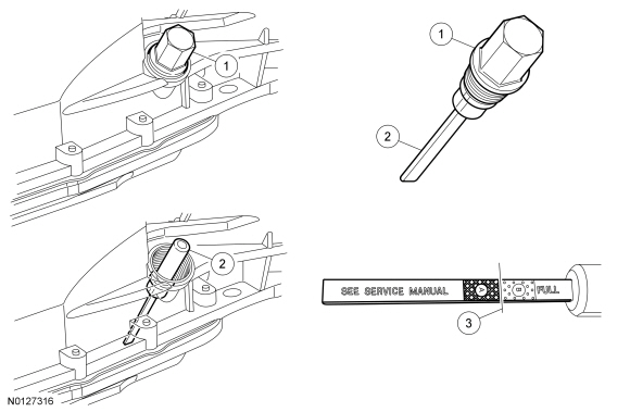
A removable dipstick-type fluid level indicator is located on the right front area of the transmission case. It is held in by an external fluid fill plug. The transmission fluid level indicator is removed with the transmission fluid fill plug. The transmission fluid level indicator is removed from the fill plug to check the transmission fluid level.
The transmission fluid level is correctly checked when the transmission is at normal operating temperature, 80ºC-85ºC (175ºF-185ºF), and the vehicle is on a level surface.
The transmission fluid level indicator has 2 areas for the fluid level, a crosshatched (labeled A) area and a dotted (labeled B) area. Use the crosshatched area when checking the transmission fluid level. The correct transmission fluid level is at the upper level of the crosshatch marks on the transmission fluid level indicator.
| Item | Part Number | Description |
|---|---|---|
| 1 | — | Transmission fluid fill plug |
| 2 | 7A010 | Transmission fluid level indicator |
| 3 | — | Transmission fluid level indicator FULL line |
Main Control Assembly
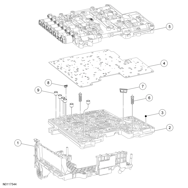
The hydraulic system of this transmission includes the fluid pump, a main control assembly and fluid passages in the transmission case and center support to apply the clutches.
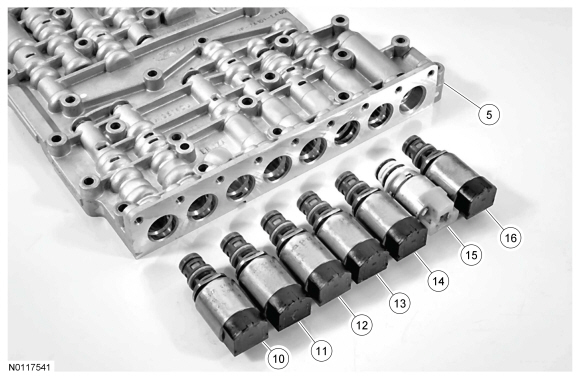
The main control assembly has an upper valve body assembly, a separator plate and a lower valve body assembly. The lower valve body assembly has 7 solenoids to control the valves in the main control.
TheTurbine Shaft Speed (TSS), Output Shaft Speed (OSS), Transmission Range (TR) and Transmission Fluid Temperature (TFT) sensors are all part of the main control assembly leadframe.
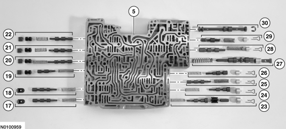
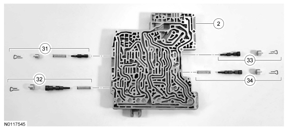
| Item | Part Number | Description |
|---|---|---|
| 1 | 7A100 | Main control |
| 1 | 7G276 | Molded leadframe |
| 2 | — | Transmission control valve body (upper) |
| 3 | 7E195 | Transmission control valve check ball (8 required) |
| 4 | 7Z490 | Transmission control valve body separator plate |
| 5 | — | Transmission control valve body (lower) |
| 6 | — | Transmission control valve assembly |
| 7 | 7H187 | Transmission control filter assembly |
| 8 | 7B155 | Transmission fluid filter |
| 9 | — | Transmission solenoid damper valve assembly |
| 10 | 7G383 | Shift Solenoid A (SSA) |
| 11 | 7G383 | Shift Solenoid B (SSB) |
| 12 | 7G383 | Shift Solenoid C (SSC) |
| 13 | 7G383 | Line Pressure Control (LPC) solenoid |
| 14 | 7G383 | Shift Solenoid D (SSD) |
| 15 | 7G484 | Shift Solenoid E (SSE) |
| 16 | 7G383 | Torque Converter Clutch (TCC) solenoid |
| 17 | — | Forward (A) clutch latch valve assembly |
| 18 | — | Direct (B) clutch latch valve assembly |
| 19 | — | Solenoid regulator valve |
| 20 | — | Low/reverse (D1) clutch latch valve assembly |
| 21 | — | Drive enable valve |
| 22 | — | Solenoid multiplex valve |
| 23 | — | Forward (A) clutch regulator valve assembly |
| 24 | — | Overdrive (E) clutch regulator valve assembly |
| 25 | — | Overdrive (E) clutch latch valve assembly |
| 26 | — | Bypass clutch control regulator valve assembly |
| 27 | — | Main regulator valve assembly |
| 28 | — | Converter release regulator valve assembly |
| 29 | — | Lubrication control valve assembly |
| 30 | — | Manual valve assembly |
| 31 | — | Low/reverse (D2) clutch latch valve assembly |
| 32 | — | Direct (B) clutch regulator valve assembly |
| 33 | — | Low/reverse (D1) clutch regulator valve assembly |
| 34 | — | Intermediate (C) clutch regulator valve |