SECTION 307-01: Automatic Transaxle/Transmission — 6R80
| 2014 Mustang Workshop Manual
|
DESCRIPTION AND OPERATION
| Procedure revision date: 01/07/2013
|
Planetary Gearset
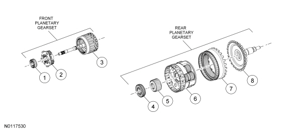
This transmission has 2 planetary gearsets (front and rear) to provide operation in reverse and 6 forward speeds.
The front planetary gearset is a single planetary gearset and has the following components:
The input shaft rotates the front ring gear as a driving member. The front sun gear is connected to the fluid pump and is held stationary. The front ring gear rotates the front planetary carrier assembly with a reduction ratio of 1.52:1.
The front planetary carrier assembly is the only output member of the front planetary gearset in reverse, 1st, 2nd and 3rd gear. The front planetary gearset provides a 1.52:1 gear ratio to the rear planetary gearset.
In 4th and 5th gear, both the front ring gear and front planetary carrier assembly are output members of the front planetary gearset. The front planetary gearset provides both a 1:1 and 1.52:1 gear ratio to different members of the rear planetary gearset.
In 6th gear, the front ring gear is the only output member of the front planetary gearset. The front planetary gearset provides a 1:1 gear ratio to the rear planetary gearset.
The rear planetary gearset is a ravigenaux planetary gearset and has the following components:
Power flow through the rear planetary gearset is as follows:
| Item | Description |
|---|---|
| 1 | Front planetary No. 1 sun gear |
| 2 | Front planetary carrier |
| 3 | Front planetary ring gear (part of input shaft assembly) |
| 4 | Rear planetary No. 2 sun gear |
| 5 | Rear planetary No. 3 sun gear |
| 6 | Rear planetary carrier |
| 7 | Rear planetary ring gear |
| 8 | Output shaft |
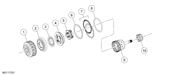
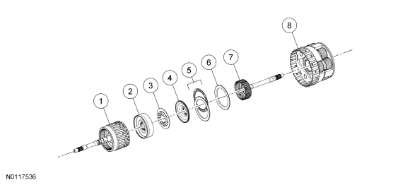
Forward Clutch (A)
The forward clutch (A) connects the front planetary carrier to the rear No. 3 sun gear. This provides a gear reduction ratio of 1.52:1 from the input shaft to rear sun gear No. 3. The forward clutch (A) is applied in 1st, 2nd, 3rd and 4th gears.
Regulated hydraulic pressure from the regulator valve in the valve body pushes the forward clutch (A) piston against the forward clutch (A) pack to apply the clutch. The front planetary carrier and the rear No. 3 sun gear are connected as a result of the clutch being applied.
| Item | Description |
|---|---|
| 1 | Forward clutch cylinder |
| 2 | Forward clutch piston |
| 3 | Forward clutch piston return spring |
| 4 | Forward clutch balance piston |
| 5 | Front planetary carrier assembly |
| 6 | Forward clutch wave spring |
| 7 | Forward clutch friction and steel plates |
| 8 | Forward clutch pressure plate |
| 9 | Rear planetary No. 3 sun gear hub and shaft assembly |
| 10 | Rear planetary No. 3 sun gear |
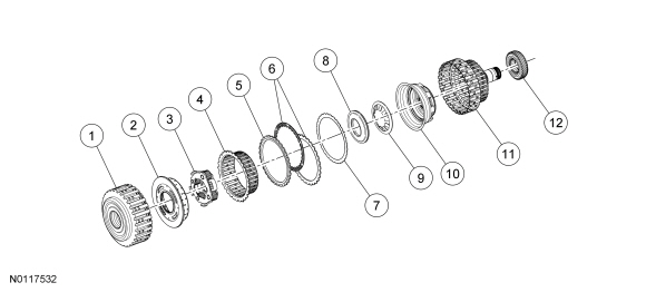
Direct Clutch (B)
The direct clutch (B) connects the front planetary carrier to the rear No. 2 sun gear. This provides a gear reduction ratio of 1.52:1 from the input shaft to rear sun gear No. 2. The direct clutch (B) is applied in reverse, 3rd and 5th gears.
Regulated hydraulic pressure from the regulator valve in the valve body pushes the direct clutch (B) piston against the direct clutch (B) pack to apply the clutch. The front planetary carrier and the rear No. 2 sun gear are connected as a result of the clutch being applied.
| Item | Description |
|---|---|
| 1 | Forward clutch cylinder |
| 2 | Forward clutch balance piston |
| 3 | Front planetary carrier assembly |
| 4 | Direct clutch hub |
| 5 | Direct clutch pressure plate |
| 6 | Direct clutch friction and steel plates |
| 7 | Direct clutch wave spring |
| 8 | Direct clutch balance piston |
| 9 | Direct clutch piston return spring |
| 10 | Direct clutch piston |
| 11 | Direct clutch cylinder |
| 12 | Rear planetary sun gear No. 2 |
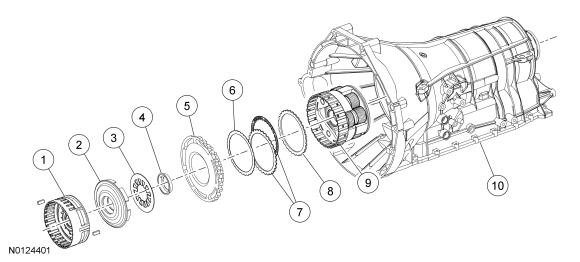
Intermediate Clutch (C)
The intermediate clutch (C) holds the rear planetary No. 2 sun gear stationary to the transmission case. The intermediate clutch (C) is applied in 2nd and 6th gears.
Regulated hydraulic pressure from the regulator valve in the valve body pushes the intermediate clutch (C) piston against the intermediate clutch (C) pack to apply the clutch.

| Item | Description |
|---|---|
| 1 | Direct clutch cylinder |
| 2 | Intermediate clutch pressure plate |
| 3 | Intermediate clutch friction and steel plates |
| 4 | Intermediate clutch wave spring |
| 5 | Intermediate clutch piston return spring |
| 6 | Intermediate clutch piston |
| 7 | Center support assembly |
| 8 | Rear planetary sun gear No. 2 |
| 9 | Transmission case |
Low/Reverse Clutch (D) and Low/One-Way Clutch (OWC)
The low/reverse clutch (D) holds the rear planetary carrier stationary to the transmission case. The low/reverse clutch (D) is applied in park, reverse, neutral and 1st gear below 5 kph (3 mph).
Regulated hydraulic pressure from the regulator valve in the valve body pushes the low/reverse clutch (D) piston against the low/reverse clutch (D) pack to apply the clutch.
The low/One-Way Clutch (OWC) is a brake clutch that holds the rear planetary carrier in one direction and allows it to freewheel in the opposite direction eliminating engine braking in 1st gear when the transmission is in drive, above 5 kph (3 mph) only.
| Item | Description |
|---|---|
| 1 | Center support assembly |
| 2 | Low/reverse clutch piston |
| 3 | Low/reverse clutch piston return spring |
| 4 | Low/reverse clutch piston retainer |
| 5 | Low/One-Way Clutch (OWC) |
| 6 | Low/reverse clutch wave spring |
| 7 | Low/reverse clutch friction and steel plates |
| 8 | Low/reverse clutch pressure plate |
| 9 | Rear planetary carrier assembly |
| 10 | Transmission case |
Overdrive Clutch (E)
The overdrive clutch (E) connects the input shaft with the rear planetary carrier. The overdrive clutch (E) is applied in 4th, 5th and 6th gears.
Regulated hydraulic pressure from the regulator valve in the valve body pushes the overdrive clutch (E) piston against the overdrive clutch (E) pack to apply the clutch.
| Item | Description |
|---|---|
| 1 | Input shaft assembly |
| 2 | Overdrive clutch piston |
| 3 | Overdrive clutch piston return spring |
| 4 | Overdrive clutch balance piston |
| 5 | Overdrive clutch friction and steel plates |
| 6 | Overdrive clutch pressure plate |
| 7 | Intermediate shaft |
| 8 | Rear planetary carrier assembly |
External Sealing
The pump assembly has a lip-type seal for the torque converter impeller hub. The pump assembly uses a large O-ring to seal the transmission case. The pump bolts also seal the pump to the transmission case.
The manual control lever shaft has a lip seal for its bore in the transmission case.
The transmission fluid pan uses a reusable gasket.
The output shaft flange has a lip-type seal that seals the flange to the transmission case.
The transmission case plug provides access to the park pawl shaft. The plug has a seal that is serviced as an assembly with the plug.
The main control leadframe connector sleeve has a seal for the transmission case bore. The seal is serviced as an assembly with the bulkhead connector sleeve.
The plug for the fluid level indicator uses an O-ring seal.

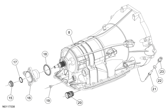
| Item | Description |
|---|---|
| 1 | Torque converter |
| 2 | Front pump oil seal |
| 3 | Front pump-to-case bolt (13 required) |
| 4 | Front pump assembly |
| 5 | Pump assembly inner oil seal |
| 6 | Front pump assembly |
| 7 | Front pump outer oil seal |
| 8 | Transmission case |
| 9 | Manual control lever shaft seal |
| 10 | Manual control lever (Manual control lever installation position is vehicle/model dependent.) |
| 11 | Manual control lever nut |
| 12 | Transmission fluid pan gasket |
| 13 | Transmission fluid pan |
| 14 | Line pressure tap plug |
| 15 | Output shaft flange retaining nut |
| 16 | Output shaft flange |
| 17 | Extension housing flange seal |
| 18 | Output shaft flange seal |
| 19 | Transmission case plug (park pawl shaft access) |
| 20 | Transmission bulkhead connector sleeve |
| 21 | Transmission fluid level indicator |
| 22 | Transmission fluid level indicator plug seal (part of transmission fluid level indicator) |
| 23 | Transmission fluid level indicator plug (part of transmission fluid level indicator) |
Bushings, Bearings and Thrust Washer Locations
This transmission supports the rotating components of the transmission with bushings, bearings and thrust washers.
The pump assembly support thrust washer controls the amount of end play for components between the pump assembly and the center support (forward/overdrive clutch assembly, direct clutch cylinder).
The T8 thrust bearing outer race controls the amount of end play for components between the center support and the rear of the transmission case (rear planetary gearset assembly, output shaft assembly).
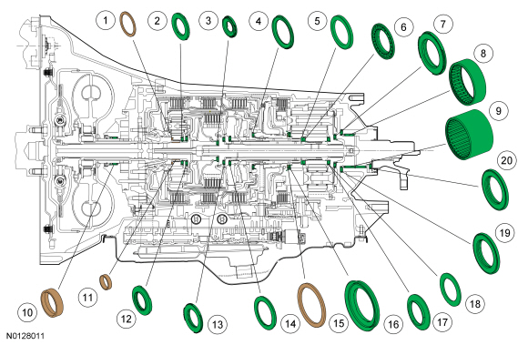
| Item | Description |
|---|---|
| 1 | Front pump selective washer |
| 2 | Bearing T1 |
| 3 | Bearing T3 |
| 4 | Bearing T6 |
| 5 | Thrust bearing outer race |
| 6 | Roller bearing T8 |
| 7 | Thrust bearing T10 |
| 8 | Output shaft bearing assembly (Four-Wheel Drive (4WD) vehicles) |
| 9 | Output shaft bearing assembly (Rear Wheel Drive (RWD) vehicles) |
| 10 | Front oil pump bushing (part of pump assembly) |
| 11 | Input shaft bushing (part of pump assembly) |
| 12 | Bearing T2 |
| 13 | Bearing T4 |
| 14 | Roller bearing T5 |
| 15 | Rear planetary carrier selective washer |
| 16 | Thrust bearing T7 |
| 17 | Roller bearing T9 |
| 18 | Outer race bearing T9 |
| 19 | Bearing T11 |
| 20 | Thrust bearing T12 ( RWD only) |
Lubrication
This transmission provides lubrication for rotating mechanical components through one main hydraulic circuit. The general flow of lubrication moves from the front of the transmission, through the input and intermediate shafts, to the rear of the transmission.
Transmission fluid from the pump assembly and the torque converter exit the transmission case to go to the transmission fluid cooler through the bottom of the transmission fluid cooler tube and returns to the transmission through the top of the transmission fluid cooler tube.
With lower transmission fluid temperatures, the thermal bypass valve in the transmission case bypasses the transmission fluid cooler tubes and redirects the fluid to the lubrication circuit. As transmission fluid temperature increases, the thermal bypass valve directs the fluid to the transmission fluid cooler.
Transmission fluid from the transmission fluid cooler or the thermal bypass valve enters the main lubrication circuit from the top of the transmission fluid cooler tube port.
Transmission fluid in the lubrication circuit flows to each of the balance pistons for the forward (A), direct (B) and overdrive (E) clutches. The balance pistons prevent unwanted clutch application when the clutch cylinder rotates at high speeds and hydraulic controls have released the clutch.
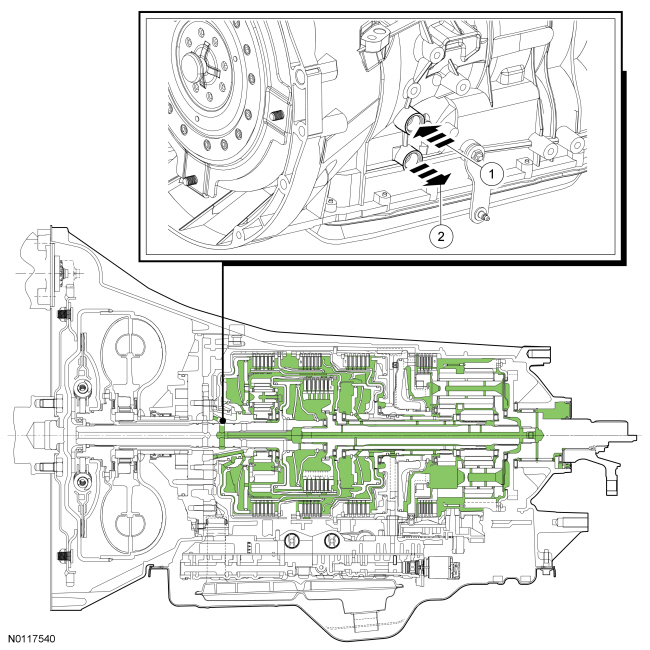
| Item | Description |
|---|---|
| 1 | Transmission fluid cooler return (inlet from the transmission fluid cooler) |
| 2 | Transmission fluid cooler pressure (outlet to the transmission fluid cooler) |
Park
The park gear is part of the output shaft assembly. The park gear has lugs on its overdrive surface that the park pawl engages to lock the output shaft.
The park lock prevents the vehicle wheels from rotating by allowing the transmission case to hold the output shaft stationary through the park pawl. When the park pawl is engaged in the park gear, the output shaft is held stationary.
When the manual control lever is rotated to the PARK position, the park lock works as follows:
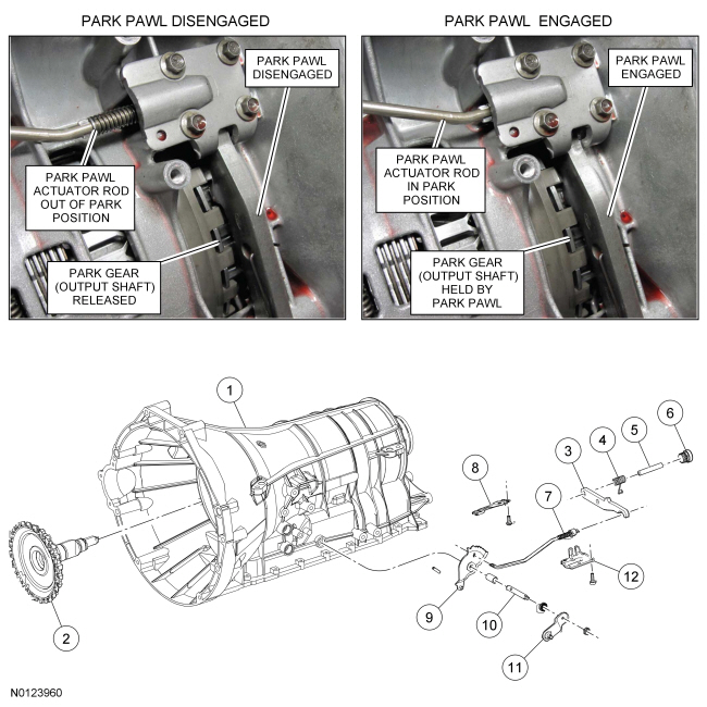
| Item | Description |
|---|---|
| 1 | Transmission case |
| 2 | Output shaft park gear assembly |
| 3 | Park pawl |
| 4 | Park pawl return spring |
| 5 | Park pawl pin |
| 6 | Plug — park pawl pin |
| 7 | Park pawl actuator rod |
| 8 | Manual valve detent spring |
| 9 | Manual valve detent lever assembly |
| 10 | Manual control lever shaft |
| 11 | Manual control lever (Manual control lever installation position is vehicle/model dependent.) |
| 12 | Park rod actuating plate |