SECTION 307-01: Automatic Transaxle/Transmission — 6R80
| 2014 Mustang Workshop Manual
|
IN-VEHICLE REPAIR
| Procedure revision date: 01/07/2013
|
| Item | Specification |
|---|---|
| Motorcraft® MERCON® LV Automatic Transmission Fluid
XT-10-QLVC (US); CXT-10-LV12 (Canada) | MERCON® LV |
NOTE: Refer to the on-line Workshop Manual to learn about using an Interactive Illustration.
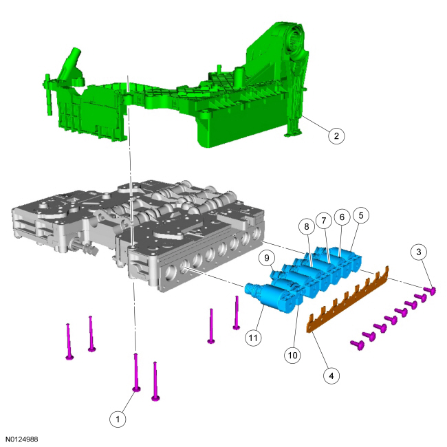
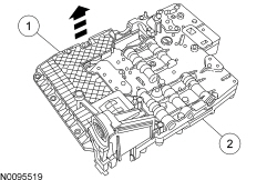
| Item | Part Number | Description |
|---|---|---|
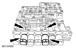
| 1 | W707884 | Main control-to-molded leadframe bolts |
| 2 | 7G267 | Molded leadframe |
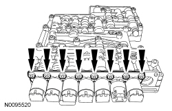
| 3 | W707885 | Solenoid hold-down bracket bolt (8 required) |
| 4 | 7Z369 | Solenoid hold-down bracket |
| 5 | 7G383 | Shift Solenoid A (SSA) Forward (1,2,3,4) clutch, normally low Variable Force Solenoid (VFS). |
| 6 | 7G383 | Shift Solenoid B (SSB) Direct (3,5,R) clutch, normally high VFS . |
| 7 | 7G383 | Shift Solenoid C (SSC), Intermediate (2,6) clutch, normally low VFS . |
| 8 | 7G383 | Line Pressure Control (LPC) normally high VFS . |
| 9 | 7G383 | Shift Solenoid D (SSD), low/reverse/overdrive clutch, normally high VFS . |
| 10 | 7G484 | Shift Solenoid E (SSE), normally off ON/OFF solenoid. |
| 11 | 7G383 | Torque Converter Clutch (TCC) normally low VFS . |
Removal
NOTICE: A Variable Force Solenoid (VFS) is calibrated from the factory and are not all the same. To replace a VFS , match the replacement solenoid type (normally high/normally low) and the band number with the original solenoid or harsh/erratic shifts, harsh/soft engagement or damage to the transmission can occur.
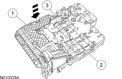
If replacing more then 1 solenoid, number the solenoids and number the main control solenoid ports to correspond to the solenoid. Pull the solenoid(s) out of the main control valve body.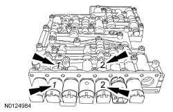
Installation
NOTICE: A VFS is calibrated from the factory and are not all the same. To replace a VFS , match the replacement solenoid type (normally high/normally low) and the band number with the original solenoid or harsh shifts or damage to the transmission can occur.
Use the solenoid exploded view at the beginning of this procedure to identify what type of solenoid is being replaced. The solenoid can be a normally high VFS , normally low VFS or an ON/OFF solenoid.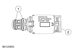
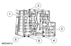
NOTE: The TR sensor pin must be aligned with the manual control valve during installation.
Position the molded leadframe on the main control.