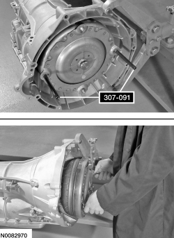
307-091 (T81P-7902-C)

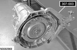
307-003 (T57L-500-B)

205-256

308-375

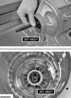
307-562 (includes 307-562/1 and 307-562/2)

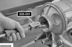
308-001 (T58L-101-B)

307-553

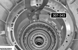
307-343 (T95P-77001-AHR)

100-001 (T50T-100-A)
SECTION 307-01: Automatic Transaxle/Transmission — 6R80
| 2014 Mustang Workshop Manual
|
DISASSEMBLY
| Procedure revision date: 02/18/2013
|
| Handle, Torque Converter
307-091 (T81P-7902-C) |
| Holding Fixture, Transmission
307-003 (T57L-500-B) |
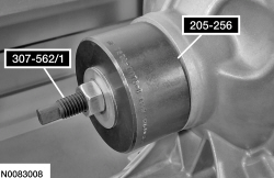
| Installer, Front Wheel Hub Oil Seal
205-256 |
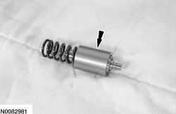
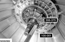
| Remover, Input Shaft Oil Seal
308-375 |
| Remover, Needle Bearing
307-562 (includes 307-562/1 and 307-562/2) |
| Remover, Pilot Bearing
308-001 (T58L-101-B) |
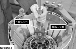
| Remover, Transmission Fluid Pump
307-553 |
| Retaining Ring Pliers
307-343 (T95P-77001-AHR) |
| Slide Hammer
100-001 (T50T-100-A) |
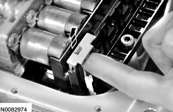
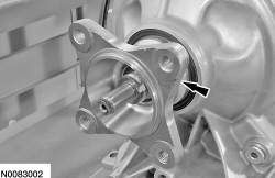
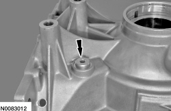
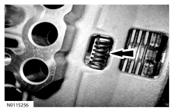
NOTE: The selective shim may come out while removing the front pump.
Inspect the back of the front pump for the selective shim and remove If necessary.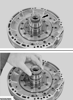
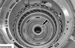
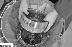
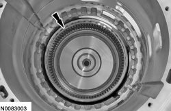
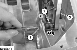
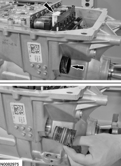
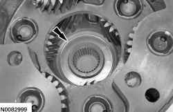
NOTE: When removing the One-Way Clutch (OWC), note the position for assembly.
Remove the OWC .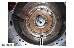
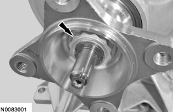
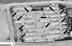
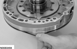
NOTE: The selective shim might stick to the T7 thrust bearing during removal of the center support.
Remove the selective shim and the T7 thrust bearing.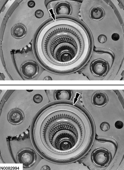
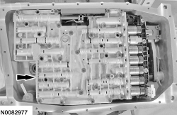
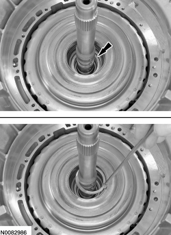
NOTE: The selective shim might stick to the back of the center support assembly during removal.
Remove the selective shim from the center support assembly.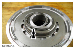
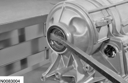
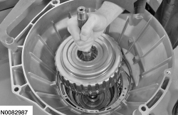
NOTE: Some of the clutch plates may stay in the case when removing the planetary carrier and the low/reverse clutch pack. Remove any clutch plates from the transmission that were not removed with the carrier and keep the clutch plates together.
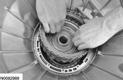
Remove the planetary carrier and the low/reverse clutch pack as an assembly.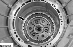
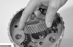
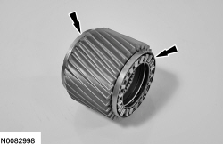
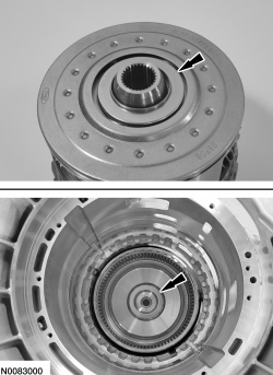
NOTE: Remove the bearings with the sun gear.
NOTE: When removing the sun gear, note that the tapered edge is facing up toward the torque converter housing.
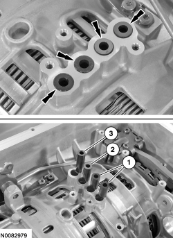
Remove the No. 3 sun gear from the planetary assembly.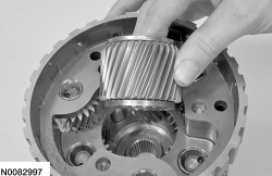
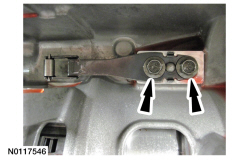
NOTICE: The output shaft flange retaining nut has been staked to prevent it from coming loose. Prior to removing the nut, remove the stake to prevent damage to the output shaft.
Place the manual control lever in the PARK position and remove and discard the output shaft flange retaining nut.