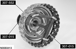
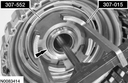
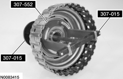
307-015 (T65L-77515-A)

307-552

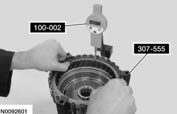
100-002 (TOOL-4201-C) or equivalent

307-555
SECTION 307-01: Automatic Transaxle/Transmission — 6R80
| 2014 Mustang Workshop Manual
|
DISASSEMBLY AND ASSEMBLY OF SUBASSEMBLIES
| Procedure revision date: 01/07/2013
|
| Compressor, Clutch Spring
307-015 (T65L-77515-A) |
| Compressor, Clutch Spring
307-552 |
| Dial Indicator Gauge with Holding Fixture
100-002 (TOOL-4201-C) or equivalent |
| End Play Gauge, Clutch
307-555 |
| Item | Specification |
|---|---|
| Motorcraft® MERCON® LV Automatic Transmission Fluid
XT-10-QLVC (US); CXT-10-LV12 (Canada) | MERCON® LV |
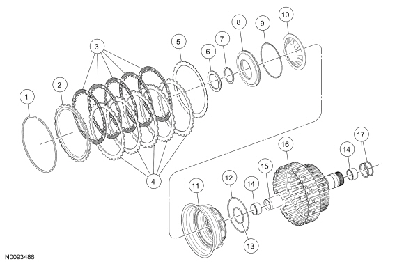
| Item | Part Number | Description |
|---|---|---|
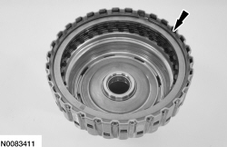
| 1 | 7D483 | Direct clutch pressure plate retaining ring |
| 2 | 7B066 | Direct clutch pressure plate (thickness model dependant) |
| 3 | 7B164 | Direct clutch internal splined friction plates (quantity model dependant) |
| 4 | 7B442 | Direct clutch external splined steel plates (quantity model dependant) |
| 5 | — | Direct clutch cushion plate (wave spring) |
| 6 | 7C096 | Bearing (T5) |
| 7 | 7A577 | Piston retaining ring |
| 8 | 7A262 | Direct clutch balance piston |
| 9 | 7A548 | Direct clutch balance piston seal |
| 10 | 7B488 | Return spring |
| 11 | 7A262 | Direct clutch apply piston |
| 12 | 7A548 | Direct clutch apply piston outer seal |
| 13 | 7C099 | Direct clutch apply piston inner seal |
| 14 | — | Direct clutch bushing hubs (part of 7F283) (2 required) |
| 15 | — | Gear shaft tube sleeve (part of 7F283) |
| 16 | 7F283 | Direct clutch cylinder |
| 17 | 7D020 | Seal shell cylinders |
Disassembly
Assembly
NOTE: Friction and steel plate quantity will vary based on engine displacement. For additional information, refer to the Clutch Plate Quantity Chart in the Specifications portion of this section.
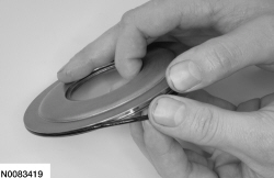
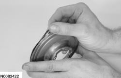
Soak the new direct clutch in clean transmission fluid.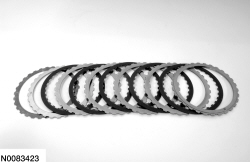
NOTE: Inspect and install a new thrust bearing as required.
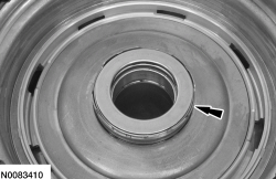
Install the T5 thrust bearing.NOTE: All direct clutch plates, friction and steel are of a wave-type design.
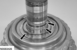
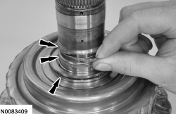
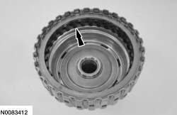
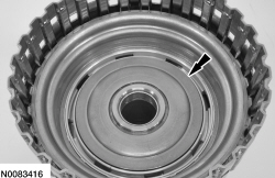
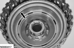
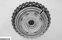
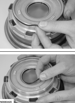
Install the direct clutch assembly into the Clutch End Play Gauge and install the Dial Indicator Gauge with Holding Fixture and position the plunger so it fits into the opening of the snap ring.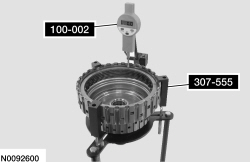
| Description | Reading |
|---|---|
| Reading A | |
| Reading B | |
| Add reading A to reading B for a total end clearance | |
| Divide the total reading by 2 for an average end clearance |
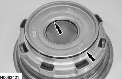
NOTE: If the final measurement is not within specification, install a new snap ring until the correct specification is achieved.